Download
1 / 35
360 likes | 604 Vues
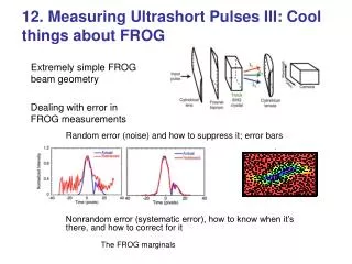
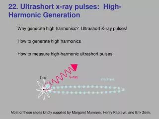
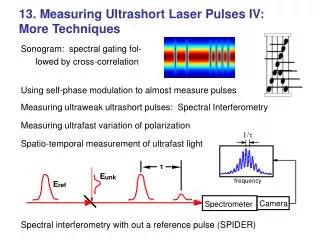
125 µm. 18. Medical Imaging with Ultrashort Laser Pulses. Multi-Photon Imaging Optical Coherence Tomography Ballistic Photon Imaging. z. 0. In linear processes, as much signal is created in the unfocused regions of the beam as at the focus.

E N D
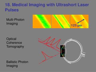
125 µm 18. Medical Imaging with Ultrashort Laser Pulses Multi-Photon Imaging Optical Coherence Tomography Ballistic Photon Imaging
z 0 In linear processes, as much signal is created in the unfocused regions of the beam as at the focus. The signal scales with the intensity (~ z–2), but the beam area ~ z2. The z-dependence cancels. In nonlinear processes, much more signal is created at the focus. The signal scales nonlinearly with the intensity (e.g., ~ z–4 or z–6), emphasizing the focus. Nonlinear-optical processes emphasize a focus. NLO signal Scanning the focus through a medium and measuring the NLO signal light yields a 3D image of NLO strength vs. position. Ultrashort pulses have high intensity for a given energy.
t t Two photon fluorescence Three photon fluorescence NLO processes used in imaging Third harmonic generation In THG, one must use a longer wavelength laser (>1.0 µm) in order to avoid direct absorption of the third harmonic by the specimen.
Two-Photon Fluorescence Imaging Pollen grain (Clivia Miniata) Conventional image (using fluorescence) ~14 µm 46 sections separated by 0.5 µm in the axial dimension. 2 seconds/image 1.5 µm axial resolution 200 mW in 16 beamlets
Two-photon fluorescence of brain tissue Living rat hippocampal neurons were stained with DiO, and imaged using pulsed illumination at 900 nm. These were imaged one day after staining and plating onto a poly-lysine-coated plastic Petri dish. The image is a projection through 50 sections of 0.3 um each. No dye bleaching was observed during scanning. The imaging had no adverse effect on the health of the cells, compared to unscanned regions in the same dish after another day in culture Steve Potter, Georgia Tech
-π/2 π/2 How Third Harmonic Light is Generated Dc(3) The tight focus provides high intensities, allowing non-linear optical effects to occur. Breaking the symmetry of the focus prevents totally destructive interference and some of the third harmonic light is emitted. Third harmonic light is produced on one side of the focus... ... and the other... but they interfere destructively. Guoy Phase Shift
Interfaces Third-harmonic generation is much stronger at interfaces. Demonstration: THG signal vs. z Note the increase in signal at the interfaces. So THG imaging yields an image of the interfaces of the specimen.
femtosecond laser sample CCD Third-Harmonic Microscopy The third harmonic of the incident light is produced when an interface breaks the symmetry of the focus, providing inherent optical sectioning. Normal optical microscope objectives are used to focus the input light and collect the TH signal light. The sample can be scanned in x and y (and maybe z) directions. Or a large beam can be used for single-shot operation (as seen here). This work has been pioneered by Squier and Muller, UCSD
Characteristics of THG imaging • Background free imaging technique, requiring no additional staining. • Provides inherent optical sectioning. • Non-fading in nature (stains fade with time). • Performed under same excitation intensities as 2-photon microscopy. • Performed in transmission. • Coherent imaging technique. • Uses IR, rather than visible or UV, so is less damaging to the specimen. • Is less bothered by phase distortions in the medium than conventional microscopy.
125 µm Detection of “Low Contrast” Interfaces Demonstration using an optical fiber in index-matching fluid. The third harmonic signal is generated at the interface of jacket and cladding; no image processing or background subtraction was used here. (~100 fs pulses at 1.2 µm, 1 kHz repetition rate.)
Orientation Dependence The different images show the fiber along different paths.
Sectional THG images of spiral algae formation • Excitation pulse: 100 fs, at 1.2 µm, at 250 kHz repetition rate. • ~1.2 mW average power at sample. • Excitation objective: 20x, 0.6 NA Zeiss Plan-Apochromat • Collection objective: 20x, 0.4 NA Olympus • Cursor: single point, rastered in a traveling Lissajou pattern. • Dispersion: ~500 fs2, which results in ~30% pulse broadening.
3D Reconstruction of Spiral Algae The THG images of the previous slide allow this reconstruction.
Third Harmonic Real-Time Imaging of Living Root 1.5 sec per frame THG cross sectional images showing motion of statoliths (Barium Titanite crystals) in a living plant root (Chara rhizoids). Motion is due to turbulence.
More Real-Time THG Images Artificial blood vessel (two cover slips) with real red blood cells flowing in it. Scanning scheme used a Lissajou pattern.
Still More Real-Time THG Images Anonymous microbes in Amsterdam canal water
A home-built THG microscope • Feature camera detection, or PMT detection for scattering media • Lock-in detection capability • Line scan rates of 1 kHz • Multiple channels for physiology • Arbitrary area scan control • About 18 inches high • Uses two input beams to cause fringes to enhance the spatial resolution
Optical Coherence Tomography Optical ranging in biological tissue can also produce an image. This work has been pioneered by Jim Fujimoto and coworkers of MIT.
Transverse Scanning Longitudinal Scanning Reflectivity Distance Optical Coherence Distance Ranging and Optical Coherence Tomography OCDR OCT Huang, et al., Science, 254 (1991)
OCT Cross-Sectional Imaging Transverse Scanning Backscatter Intensity Axial Scanning (Depth) Tissue Specimen Huang, et al., Science, 254 (1991)
Source / 2 Low Coherence Interferometry Reference Michelson Interferometer Sample Detector Low-Coherence Source High-coherence Source Coherence Length Detector Detector Mirror Displacement Mirror Displacement
SLD or KLM Laser Sample D 1 Prisms Reference D mirror 2 + - Band Pass Envelope A-D Computer Filter Detector Fiber-Optic Interferometer for OCT An all-fiber system can be constructed. The two detectors see opposite-phase fringes, so subtracting their signals doubles the signal and subtracts off noise.
Retinal Imaging – Normal Human Subject At the moment, ophthalmologists essentially use flashlights and look for shadows. Or they take low-contrast photographs. Hee, et al., Ophthalmology 102 (1995)
OCT can see otherwise invisible micro-tears in the retina Photographs can’t see the tears
Dorsal Ventral A C ey h g B D m i ea Reflectance 1 mm Measurements of a live tadpole Boppart, et al., Dev. Biology 177 (1996)
Ultrasound Image OCT Image Cardiovascular Imaging: unstable plaque in vitro Comparison of OCT and ultrasound Unstable plaque has a thin wall of less than 100 microns and is prone to rupture. Standard OCT with its resolution of 15 microns provides a significant improvement over conventional ultrasound with a 100 micron resolution. Brezinski, et al, Circulation 93 (1996)
Ex Vivo OCT Imaging of Cervical Cancer Invasive Carcinoma Normal Cervix Carcinoma In Situ e e Ultrasound 500 μm 500 μm 500 μm OCT Pitris, et al, Obstetrics and Gynocology 93 (1999)
1 3 2 4 5 6 Real-Time OCT Imaging (African frog heart in vivo ) Log Reflectivity 500 µm Images of 512 pixels square can be acquired 4 to 8 frames per second. Tearney, et al., Opt. Lett. 21 (1996)
In vivo Ultrahigh Resolution OCT Xenopus laevis (African frog tadpole) 100µm 1 x 5 µm (long. x trans.); 0.54 x 2 mm; 1200 x 1000 pixels Drexler, et al., Opt. Lett. 24, (1999)
OCT IVUS Inside a blood vessel (in vitro) The OCT images have significantly higher resolution than intravascular ultrasound (IVUS). Brezinski, et al., Am. J. Cardiology 77 (1996)
Features of Optical Coherence Tomography • Cross-sectional micron-scale imaging • In situ and in real time, without the need for tissue excision and processing • Catheter / endoscope imaging of internal organs • Consistent with Minimally Invasive Surgery • Electronic information enables processing, storage, transmission • Commercial device available for ophthalmologists
Ultrafast Ballistic-Photon Imaging Multi-photon and OCT imaging work well when the medium is nearly transparent. Unfortunately, most tissue is opaque due to massive amounts of scattering. It’s easy to image when light rays travel straight through a medium. But when they scatter randomly, how do you image anything? Most medical imaging problems (e.g., mammography) are plagued with scattering. Even x-rays are scattered significantly. This is a major unsolved problem.
The long way! The short way! Ultrafast Ballistic-Photon Imaging 2 Since scattering is probabilistic, there will usually be some photons that experience no scattering and pass straight through the medium. Note that rays that travel straight through a medium take the least time. A tortuous path with many scatterings takes much longer. So illuminate the medium with an ultrashort pulse and time-gate the transmitted beam, detecting only the photons that arrive earliest (i.e., that pass straight through).
Ultrafast Ballistic-Photon Imaging 3 The transmitted light will have a fast “ballistic” component, followed by a slower diffuse scattered component. Using ultrafast time-gating to detect only the ballistic component will yield an image of absorption vs. transverse position.
Ultrafast Ballistic-Photon Imaging 4 Unfortunately, the ballistic component is weak, as most light is scattered away. If Ls is the mean free path for photons, the energy of the ballistic photon pulse, Uballistic, is: Uballistic = Uincidentexp(–L / Ls) where L is the sample length and Uincident is the incident pulse energy. Example: Suppose we wish to perform mammography. Human breast tissue has Ls ~ 0.5 mm. If the breast is only 25 mm thick, then exp(–L / Ls) = exp(–50) = 10–22 Using 1 J = 1019 photons, the ballistic component has less than one photon! Ballistic-photon imaging has achieved only limited success.