Download
1 / 1
10 likes | 116 Vues
Investigating wireless communication challenges on naval ships and evaluating test results using signal processing metrics and the WARP platform. Testing conducted in various ship locations to study RF characteristics.

E N D
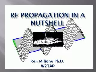
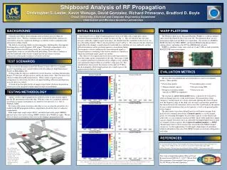
Shipboard Analysis of RF Propagation Christopher S. Lester, Kevin Wanuga, David Gonzalez, Richard Primerano, Bradford D. Boyle Drexel University, Electrical and Computer Engineering DepartmentData Fusion and Wireless Systems Laboratories BACKGROUND INITIAL RESULTS WARP PLATFORM Currently, most below-deck communications networks on naval ships are connected by wires. Wireless communications would add flexibility and increase survivability; however, significant challenges to reliable wireless communications onboard naval ships remain. The hull of a naval ship exhibits an electromagnetic shielding effect that impedes the propagation of radio frequency (RF) signals. Watertight compartments often show high isolation from RF energy while the reverberant nature of ship compartments results in considerable multi-path fading. These effects combine to limit the bandwidth of the wireless channel and disrupt wireless network connectivity, reducing the usefulness of wireless networks. One initial test was a chirp test performed from 2.40 to 2.42 GHz, with a single pure carrier waveform being transmitted from a single location (see Fig. 1). This test indicates that, for some locations within the complex engine room space, the channel from the transmitter to the receiver was not a flat-fading channel. This is seen for positions 4 and 7 in Fig. 2. This indicates that the coherence bandwidth of the channel is smaller than the bandwidth over which the test was conducted, and that different frequencies in the spectrum experience uncorrelated fading. This frequency-selective fading results from multi-path signals at certain frequencies combining at the receiver antenna in a manner in which one multi-path signal cancels out another. This effect is to be expected given the electrically-large reflective space that makes up the compartment in the ship. The image at right is a computer-generated visualization of the complex cavity standing wave pattern developed within an actual Navy ship space [1]. The simulated data shows power fluctuations on the order of 25 dB in the electromagnetic field strength patterns for a similar space to the engine room in which we tested. The Wireless Open-Access Research Platform (WARP) is a software defined radio testbed developed by Rice University [2]. This platform allows for fast prototyping of physical and MAC layer algorithms. Our interface to WARP in MATLAB allows for SISO, MIMO, and Spatial Multiplexing physical layers (among others), and mimics the 802.11g OFDM frame structure. WARP is a modular system; radio cards in 2.4 and 5 GHz are built around the MAX2829 RF transceiver chipset. TEST SCENARIOS The test site for this project is the USS Thomas S. Gates (CG-51), a currently-inactive Ticonderoga-class cruiser berthed at the Naval Inactive Ship Maintenance Facility in Philadelphia, PA. Testing within the ship was conducted in several locations, including the helicopter hangar, 2nd deck port side passageway, and the aft engine room. These locations were chosen for their diverse RF characteristics. With a variety of point-to-point arrangements to select from, the effects of signal shielding, reflection and dispersion were all able to be studied. A sketch of the floor plan for the aft engine room (below) illustrates the positions of the receiver for one point-to-point signal test that was performed. EVALUATION METRICS The tests that are performed are assessed based on a variety of evaluation metrics. These include: The creation of a power delay profile allows a channel to be evaluated in terms of channel gain over a time and frequency. By transmitting a chirp (frequency varying signal) or a sweep signal and capturing the received signal over the frequency range of the chirp, one can create a power delay profile for the channel between the transmitter and receiver. This would indicate the amount of inter-symbol interference that can be expected, as well as the general quality of the channel. The other metrics have been defined based on well known concepts from packet-based communication theory. Channel capacity is a useful channel metric for estimating throughput, because while capacity is only theoretically achievable, it is an asymptotic function of SNR, which would imply that a higher capacity channel will always have an achievable throughput higher than or equal to a channel of lower capacity. The reciprocal condition number is a MIMO channel metric that is used to measure how uncorrelated the MIMO channel streams are; A value approaching 1 would imply a high degree of correlation, which would indicate that each of the MIMO streams are relatively orthogonal to each other. • Power delay profile • Shannon channel capacity • Reciprocal condition number (specific to MIMO arrangements) • Constellation plots (visual) • Post-processing SNR • Packet error rate TESTING METHODOLOGY Agilent wireless signal equipment was utilized in order to inject known signals into the RF environment aboard the ship. With this setup, we can generate arbitrary waveforms or signals conforming to any number of set protocols (e.g.: 802.11, WiMAX, GSM). By testing with various locations in the ship, we can ascertain the parameters of a model for the RF propagation within a compartment aboard the ship or to adjacent compartments. Both single-input-single-output (SISO) and multi-input-multi-output (MIMO) physical layers were used in testing (MIMO with the aid of WARP, see right). We are able to evaluate several metrics that assist in developing a propagation model. REFERENCES [1] G. B. Tait and M. B. Slocum, “Electromagnetic Environment Characterization of Below-Deck Spaces in Ships,” in Proc IEEE Int. Symp. Electromagnetic Compatibility (Detroit, MI), August 2008. [2] Rice University, “Wireless Open-Access Research Platform (WARP),” http://warp.rice.edu, 2009. Fig. 2: The plots on the left show spectrograms of the received signal strength for one chirp. The average signal amplitude over five chirps is shown in the plots on the right. Receiver positions correspond to the locations shown in Fig. 1. Fig. 1: Floor plan sketch of the aft engine room illustrating positions of the receiver for each of seven testing locations. The transmitter remained stationary throughout testing. For clarity, machinery has been omitted. This work is funded through the Office of Naval Research award N00014-11-1-0327 “Below-Deck Electromagnetic Environment Characterization For RF Wireless Network Operation.”