Download

1 / 71
750 likes | 1.31k Vues
Antenna Fundamentals. Antenna Theory and Measurements with the Model 8092 System. FEATURES. Low cost complete antenna measurement system. No anechoic chamber required to obtain good results. Covers several antenna technologies. 1GHz and 10GHz operation.

E N D
Antenna Fundamentals Antenna Theory and Measurements with the Model 8092 System
FEATURES • Low cost complete antenna measurement system. • No anechoic chamber required to obtain good results. • Covers several antenna technologies. • 1GHz and 10GHz operation. • Usable from 1GHz to 30GHz with separate generators. • Software can be used in stand-alone mode. • Unique options: phasing system, Rotman lens based multi-beam array antenna.
Background • Maxwell (1831-79) Fundamental equations. (Scottish) • Hertz (1857-94) First aerial propagation (German) • Marconi (1874-1937) Transatlantic transmission (Italian) • DeForest (Triode tube 1920) Signal generators (American) • World War II (1939-45) Intense war-driven development
Definitions • An antenna is a device for radiating or receiving radio waves. Antennas act as the transition between waveguides or transmission lines and free space.
Definitions • An isotropic source is a hypothetical antenna which is non(all)directional, that is, which has equal radiation intensity in all directions • The dipole antenna is a simple type of antenna consisting of two rods or wires. The length of this antenna is L. The dipole is connected at the center to the transmitter through a transmission line.
The Dipole Antenna Note balanced transmission line
Definitions • The current distribution, that is the magnitude of the alternating current along the length of a dipole antenna, is not necessarily uniform. Instead, it is zero at the ends, and may be highest at the center or at other points.
Definitions • An ideal dipole is another hypothetical antenna which is useful in the study of antennas. It can be considered to be a dipole of infinitesimal length with a uniform current distribution. The theoretical characteristics of an ideal dipole approximate those of electrically small dipole antennas.
Definitions • A radiation pattern is a three-dimensional, graphical representation of the far-field radiation properties of an antenna as a function of space coordinates. The far-field region is a region far enough for the radiation pattern to be independent of the distance from the antenna. The radiation pattern of a particular antenna can be measured by experiment or can be calculated, if the current distribution is known.
Definitions • Although the term "radiation" pattern is used, it applies just as well to receiving antennas. The reception pattern of an antenna is identical to its radiation (transmission) pattern. This is a general rule, known as the reciprocity theorem.
Definitions • Although the complete radiation pattern is a three-dimensional function, a pair of two-dimensional patterns are usually sufficient to characterize the directional properties of an antenna. In most cases, the two radiation patterns are measured in planes which are perpendicular to each other. A plane parallel to the electric field is chosen as one plane and the plane parallel to the magnetic field as the other. The two planes are called the E-plane and the H-plane, respectively.
Definitions • The half-power beamwidth (HPBW) of an antenna is the angular separation of the points in the main beam where the power equals one-half (-3 dB) the power radiated in the direction of maximum power
Theoretical E-plane Radiation Pattern of an Ideal Dipole Showing the Half-power Beamwidth
Radiation Pattern Characteristics • 3 dB beamwidth • Sidelobes • Nulls • Front-to-back ratio • Gain (approximate) • Maximum signal position
Far Field Conditions • How far is far enough? • If D >2.5λ then • If D<λ/3 then • If λ/3 < D < 2.5λ then rff>5D
Antenna Input Impedance • Input Impedance (resistance + reactance) • Radiation Resistance (corresponds to energy that is transmitted) • Loss Resistance
Antenna Input Impedance Input resistance (red line) and reactance (green line) of a dipole antenna as a function of antenna length
Baluns • BALanced to UNbalanced device • Similar to transformers • Used at RF • Usually band-limited • Improve matching and prevent unwanted currents on coaxial cable shields
Baluns Balun for connecting a center-fed dipole to a coaxial cable
Baluns As Impedance Transformers Transition from a 50Ώ coaxial cable to a 300 Ώ half-wave folded dipole through a four-to-one impedance transformation balun
Yagi (Parasitic) Antennas • Remember the near-field equations • The near-fields can be used to induce currents in adjacent antenna elements • With the proper delay (spacing and lengths), phases can be obtained that will add in certain directions and cancel in others • Reflector elements and director elements are thus used to give directivity to an antenna
Graph of gain versus the total number of elements of a typical Yagi antenna
Gain of a Yagi antenna for different numbers of elements (spacing = 0.5 λ)
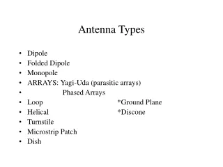
Other Antennas • Other dipoles • Monopole • Helical • Loop (electrically small & large)
Radiation patterns of the λ dipole (a) and the 3 λ /2 dipole (b)
Image Theory (a) Dipole over a perfectly conducting plane (b) Equivalent model with image theory
Helical Antenna (d~λ) Axial-mode helical antenna : (a) geometry, (b) pencil-beam radiation pattern
Helical Antenna (d<<λ) Normal-mode helical antenna: (a) geometry, (b) radiation pattern
Patch Antenna Microstrip patch with microstrip transmission-line feed
Single Patch Antenna in the Antenna Training and Measuring System
Overview of Lab-Volt Antenna Measurement System • Complete system to build antennas and to measure antenna patterns • 2 ranges of operation (1 GHz and 10GHz) • With separate generator, can be used from 1GHz to over 30GHz • Contains wire antennas & aperture antennas
Wire Antennas versus Aperture Antennas • Wire antennas are usually operated at frequencies where the wavelength is larger than or approximately equal to the antenna length. Ex: dipoles, monopoles, folded dipoles…(λ≥L) • Aperture antennas are usually operated at frequencies where the wavelength is smaller than the antenna dimension. Ex: Horn antennas, parabolic reflectors, patch antennas…(λ≤L)