Download
1 / 8
80 likes | 185 Vues
The beam position monitor features two identical modules of linear hodoscopes with multi-channel fibers. Each module forms a plane perpendicular to the photon beam and is mounted on a remote-controlled table behind HYCAL. The detector structure consists of scintillating fibers transmitting light through light guides to be detected by Hamamatsu PMT's. A compact electronics module provides 64 amplifier and discriminator channels for anode signals, which are converted to ECL readout. Gain normalization is crucial for maintaining stable results during the run, with online monitoring options available through a GUI. Running the BPM monitor online involves accessing the GUI and ensuring proper settings for beam position and gain normalization. The EPICS system further aids in tracking and displaying beam positions accurately. Marks on the detector assist in survey purposes.

E N D
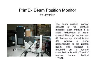
The beam position monitor consists of two identical modules. Each module is a linear hodoscope of multi-channel fibers (X module has 61 channels and Y module has 62) forming a plane perpendicular to the photon beam. This detector is mounted on a remote controlled table with (X and Y motion) located behind HYCAL. PrimEx Beam Position Monitor By Liping Gan
Structure of detector • Each scintillating fiber has dimension of 2X2X13 mm3. The scintillating light from the fibers transmit through the light guide and is detected by four 16-channel R5600-M16 Hamamatsu PMT’s. A compact electronics module provides 64 channels of amplifier and discriminators for anode signals, then convert them to ECL readout through a time-over-threshold circuit. The ECL signals are sent over to SIS3801-256-flat scalars and read into epics systems
Voltage setting The R5600-M16 PMT has substantial gain variations among the different pixels, so a nominal initial HV setting for the PMTs was determined based on the average behavior. Then a gain map was calculated by normalization of the gain using cosmic ray data. As a result, the HV setting should not be changed during the run.
Online monitoring During the run, the x and y beam positions are displayed through a GUI. There are three options that you can select: • “Raw” will display beam profile by using raw data; • “accumulate” will accumulate the counts from the raw data. We only use this option for the gain calibration; • “Smooth” will apply the gain normalization factors to the raw data and fit the profile distribution. Please make sure to select the mode “smooth” only during the run so that the gain normalization factors will be applied to the data!!!
How to run BPM monitor online • Login clon01 as “clasrun” user. • Type “medm –x $APP/primex_profiler/medm/pg_profile.adl” to bring up the GUI • Click the “gp HV” button to open HV GUI, make sure the HVs are turn on with the correct voltage values. • Click the “gp motor” button to open motion control GUI to make sure the beam hitting the center area of the detector ( the area ofchannel 25-45 for both x and y are recommended) . • Select mode “smooth” on the PrimEx BPM GUI so that that the gain normalization factors will be applied to the display.
Conversion factor Conversion factors from the fiber channel number to x and y position displayed on the GUI for LG_BPM are: • X position on GUI =2*[x fiber chan#]-61 • Y position on GUI =2*[y fiber chan#]-61
Marks on detector • There are marks on the detectors for survey purpose. The mark positions on x module is at fiber channel