ITER Internal Components
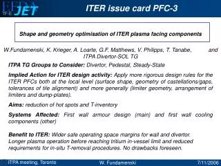
Modules 7-10. TBM Frame and Dummy TBM. Outer frame. Inner frame. Modules 11-18. Modules 1-6. Shield Block. ~850 – 1240 mm. Summary. Dummy TBMs. ~1240 – 2000 mm. FW Panel.

ITER Internal Components
E N D
Presentation Transcript
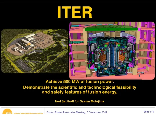
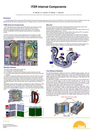
Modules 7-10 TBM Frame and Dummy TBM Outer frame Inner frame Modules 11-18 Modules 1-6 Shield Block ~850 – 1240 mm Summary Dummy TBMs ~1240 – 2000 mm FW Panel The ITER plasma-facing components (PFCs) directly face the thermonuclear plasma and cover an area of about 850 m2. They include the Divertor, the Blanket and the Test Blanket Modules with their corresponding frames. This paper gives an overview of the ITER Internal Components and outline their design and procurement status. ITER Internal Components Divertor The main function of the divertor is minimizing the helium and impurity content in the plasma as well as exhausting part of the plasma thermal power. The ITER divertor consists of 54 cassette assemblies, with a total mass of 470 tons, and a plasma-facing surface area of ~ 210 m2. Each cassette assembly includes one Cassette Body (CB) and three PFCs, namely the inner and outer Vertical Targets (VTs), and the Dome (DO). The divertor CB is reusable to minimise activated waste; it provides neutron shielding, routes the water coolant and supports the different PFCs. The inner and outer VTs are the PFCs, which in their lower parts directly interact with the plasma scrape-off layer and in their upper parts act as baffles for the neutrals. The DO protects the CB from plasma radiation, baffles the neutral, particularly helium, allows transient movements of the strike points and provide improved operational flexibility of the divertor in terms of magnetic configuration. Following the successful completion of the R&D and qualification technology phase, the Divertor reached a stage of maturity to allow the start of its construction in 2009. - The ITER plasma-facing components (PFCs) directly face the thermonuclear plasma and cover an area of about 850 m2. They are some of the most technically challenging components of the ITER machine. They include the Divertor, the Blanket and the Test Blanket Modules with their corresponding frames. The PFCs consist of a plasma facing material (armour) mounted onto a heat sink and supported by a structural/shielding material. The total thermal power, which is deposited onto the PFCs, can reach a value of 850 MW and is removed by pressurized water. ITER Internal ComponentsM. Merola1, D. Loesser2, R. Raffray1, L. Giancarli11) ITER Organization, CS 90 046, 13067 St Paul-lez-Durance Cedex France, 2) Blanket Integrated Product Team, Plasma Physics Laboratory, Princeton University, Princeton, NJ 08543 USA Blanket System • The main functions of the blanket system are: • to exhaust part of the plasma power, • to contribute in providing neutron shielding to superconducting coils and • to provide limiting surfaces that define the plasma boundary during startup and shutdown. • The system comprises two different sub-systems that cover the ITER inner vessel wall. The wall-mounted blanket modules covering 620 m2 and the port-mounted blanket modules covering 40 m2, which are not described in this poster. The wall mounted blanket modules (BMs) consist of two major components, a plasma-facing First Wall (FW) panel, with a beryllium (Be) armour, supported by a Shield Block (SB). • The Blanket system has been subject to a substantial re-design following the ITER Design Review of 2007. The Blanket CDR in February 2009 has confirmed the correctness of this re-design and the effort is now focused on finalizing the design work and the supporting R&D programme in view of the start of procurement late in 2012. Test Blanket Modules The Test Blanket Modules (TBMs) are mock-ups of DEMO breeding blankets. They are installed in three ITER equatorial ports (Nos. 2, 16 and 18) devoted to TBM testing, each of them allocating two TBMs, inserted inside a steel frame. The TBMs and the related TBM programme is described elsewhere. Here, only a description of the TBM frame and dummy TBM will be given. The TBM frame is a water-cooled 316L(N)-IG steel port structure. It has a radial length of 3,250 mm, a poloidal height of 2,160 mm and a toroidal width of 1,710 mm. It can accommodate up to two TBMs, having a plasma-facing surface of 484 (toroidal) x 1,660 (poloidal) mm2. Behind each TBM, there is a shield block that has a function to protect the cryostat/magnets region. Both components form the so-called TBM-Set. The TBM frame comprises two parts: a structural part, called the “outer frame”, and a shield part, the “inner frame”. These are steel fabricated structures, where the cooling channels are obtained by drilling. The outer frame has a design similar to that of the ITER generic equatorial port plug frame and is obtained by welding 60 mm thick plates. It is welded to the equatorial port closure plate. The inner frame is bolted inside the outer frame and has a more massive structure with 155 mm wall thickness. It has the function to neutronically and thermally insulate the two TBMs between themselves and from the surrounding environment.