Download
1 / 7
70 likes | 199 Vues
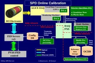
This technical overview details the implementation of Local Data Concentrators (LDCs) for machine monitoring and calibration within complex DAQ systems. It explores the configuration of FED servers, optical communication via VME, and data storage processes within the OCDB. Key components include online calibration algorithms, noise filtering for pixel detection, and the integration of trigger conditions for optimal performance. Discussion also covers simulation of Fast-OR signals and the production of CTP inputs, outlining the processes and parameters necessary for effective data management and analysis.

E N D
RO Electronics Data ALICE DAQ Local Data Concentrators (LDCs) Monitoring Machines Monit. Machine Reference Data Displayer GUI Config. DB Control FED Servers (x2) Optical VME Ethernet (DIM) Comm.& Status PVSS FED control OCDB Reference data storage SPD Online Calibration Detector Algorithms (DA) a) Standalone Runs b) Physics Runs DA a DA b Reference Data DAQ network DAQ FXS DCS network ThresholdsNoisy pixels Delays Offline network Shuttle Pre-processing DCS Pre-processing NoisyDeadpixels Reference Data Displayer GUI A.Mastroserio , H.Tydesjö
SPD Online Calibration Readiness Output to OCDB A.Mastroserio , H.Tydesjö
Pixel Trigger Conditions Transfer Scheme RO Electronics Fast-OR Signals CTP Inputs OCDB ECS SOR, run number Pixel Trigger System (PIT) CTP Trigger conditions (Text Format) DCS FXS Offline network Trigger conditions (OCDB Format) Shuttle Trigger Preprocessor PIT Conditions A.Mastroserio , H.Tydesjö
Pixel Trigger Conditions Transfer Scheme • Information to transfer to DCS FXS (text file format) • Configuration version • Algorithms in use: Logical functions and their parameters • List of active chips Trigger preprocessor Translate text file into OCDB Root file, (Class taking care of active chips already present in AliRoot) A.Mastroserio , H.Tydesjö
Algorithms available (now) • I := number of active FO on Inner layer • O := number of active FO on Outer layer A.Mastroserio , H.Tydesjö
PIT Simulation Fast-OR Signals CTP Inputs Digits OCDB Implementations of all the logical functions Should also go into simulated raw data AliITSTrigger Fast-Or Signal Generator PIT Processor AliCentralTrigger Fast-OR efficiency Noise probability PIT Conditions A.Mastroserio , H.Tydesjö
AliITSTrigger • Add AliTriggerInputs • Produce CTP inputs in method “Trigger” by procedures A and B below(No need to limit the number of inputs, as in real operation) • A) Fast-OR signal generator • Convert digits to 1200 bits (one for each pixel chip) • Input from OCDB: • Probability of noisy Fast-OR signal (per chip) • Efficiency: “pixel hit Fast-OR signal” (per chip column) • default: 0 noise and 100% efficiency • to be measured from data analysis in the future • B) PIT processor • Produce the CTP inputs based on each of the logical functions • Input from OCDB: • Trigger conditions (active chips, parameters for logical functions) A.Mastroserio , H.Tydesjö