Download
1 / 30
320 likes | 519 Vues
E906/Drell-Yan Collaboration Meeting, 7 January 2009 Holiday Inn Express, Los Alamos, NM http://www.phy.anl.gov/mep/drell-yan/E906_internal/Meetings/09Jan/index.html. Status of CR Latch, Pre-Amplifier Discriminator Modules. Wen-Chen Chang 章文箴 Institute of Physics, Academia Sinica.

E N D
E906/Drell-Yan Collaboration Meeting, 7 January 2009 Holiday Inn Express, Los Alamos, NM http://www.phy.anl.gov/mep/drell-yan/E906_internal/Meetings/09Jan/index.html Status of CR Latch, Pre-Amplifier Discriminator Modules Wen-Chen Chang 章文箴 Institute of Physics, Academia Sinica
Taiwan group Members: • Institute of Physics, Academia Sinica: Wen-Chen Chang, Ping-Kun Teng, Yen-Chu Chen, Da-Shung Su (engineer), Bo-Ru Lin (research assistant), Shiuan-Hal Shiu (Ph.D. student) • Ling-Tung University: Ting-Hua Chang • Possible manpower in the future: Jia-Ye Chen (postdoc), Su-Yin Wang (Ph.D. student) Committed responsibility: • Build 400 preamplifier-discriminators cards (6400 channels in total) for 5500 tracking channels in Station 1 MWPC and for 400 channels Proportional tubes in Station 4, • Build the readout system for Coincidence Registers (CR), which consists of 110 CR modules (7040 channels in total) for 5500 tracking channels in Station 1 MWPC, for 400 channels of Proportional tubes in Station 4, and for 320 channels of hodoscope planes in all stations, • Participate in the LVL2-Trigger project – two CEAN V1495 FPGA logic units purchased and one Ph.D. student will be available in the early summer to work on this project.
Preamp/Discriminator Cards Hodoscopes Trigger Interface VME SBC ROC VME SBC ROC Ethernet Connection Readout Controller VME Latch crates Ethernet Connection CODA rcServer To DATA Storage Configuration of MWPC and Readout Electronics Cables to Latch System MWPC Prop. Tubes Fast Ethernet Switch hub
Requirement of Specs • Latch signal – 53 MHz clock of Main Injector RF. • 200 triggers/per spill; 1kHz trigger rate aimed for DAQ. • Level-2 trigger latency: “Master Trigger OR” decision time is about 91ns. • Depth of shift register needed for : • LVL-2 latency: 53MHz*91ns~ 5 clocks. • Delay due to cable length of LVL-2 trigger signal. • There is a 1k-depth in the current design of FPGA, corresponding to 20sec delay with 53MHz clock. • Depth of memory buffer for LVL-2 events: • 200 events for one spill. • There is2k-depth in the current design of dual-port SRAM. • VME transfer throughput: • 64 bits*1kHz*20 Modules/per crate=160 kB/per sec << VME 160(320) MB/sec. • Deadtime-free is possible.
Block Diagram of Coincidence Register readout MWPC 5500 channels 16-channel PreAmp/ Discriminator Card 64-channel VME 6U CR Module Connector Twisted-pair cable DAQ Extend Memory Buffer (DP-SRAM) 16-bit ECL #1 16-bit ECL #2 Latch array 16-bit ECL driver 64-bit ECL-TTL transceivers Shift register VMEbus Backplane VME Agent 16-bit ECL #3 FPGA 16-bit ECL #4 RF(Level-1 trigger) signal Level-2 trigger
FPGA design Hardware device: Actel 1.5V ProASIC3 series A3P1000 (1M system gates, 144Kbits embedded RAM) Live at Power-up support. Design software: Actel Libero-IDE 64-bits ECL-TTL translators 32-bits width Dual-Port SRAM A01~A31, D0~D31, DS0, DS1, AS, Write, DTACK 32-bit width Asynchronous FIFO Status & Control Registers 1k depth of 64-bit width shift-register 64-to-32 Multiplexer 1depth of 64-bit width latch array VMEbus transceivers VMEbus Agent RFx2 RF L2 trigger FPGA RF(Level-1 trigger) signal 6 channel ECL control I/O Level-2 trigger Busy signal
Coincidence Register (CR) modules Front panel VME Backplane JTAG-ICE ARM processor AT91SAM9260 Transceiver DM9161 Ethernet 10/100Mbps A01~A23, D0~D15, DS, AS, Write, DTACK VME bus P1 COM port 256MB x 16 NAND Flash [5] Bus buffer x5 [6] 16 Debug UART 64MB SDRAM 64MB SDRAM 4Kbit x 32 DP-SRAM [3] 64MB x 32 SDRAM [4] - + 16ch ECL inputs 16ch ECL inputs The definition of ECL connector 1 FPGA Actel A3P-1000 64ch ECL to TTL [2] A32, Addressing rotary switches 16ch ECL inputs 16ch ECL inputs 6ch ECL control I/O Bus buffer x3 [6] A24~A31 D16~D31 JTAG 8ch TTL to ECL [1] VME bus P2 Trigger, Fast clear Reset [1] ON Semiconductor, MC10H124 [2] ON Semiconductor, MC10H125 [3] IDT, IDT70V24, 4Kbit x16 Dual-Port SRAM [4] Winbond, W9825G6, 256Mbit x16 SDRAM [5] Micron, MT29F2G16AACWP, 2Gb x16 NAND Flash [6] TI, SN74VMEH22501A, VME bus transceiver 2ch NIM I/O NIM/ECL ↔ TTL CLK DATA x x x x
Power distribution for CR module Front panel VME Backplane 1.8V power regulator for ARM core Ethernet 10/100Mbps +3.3 V power regulator VME bus P1 + 5V 1.5V power regulator for FPGA core Debug UART 16ch ECL inputs 16ch ECL inputs + 3.3V Area 64ch ECL to TTL 16ch ECL inputs 16ch ECL inputs 6ch ECL control I/O +/- 5V Area -5V power regulator 8ch TTL to ECL VME bus P2 -12V 2ch NIM I/O NIM/ECL ↔ TTL
Operation Flowchart of CR latch module Start Start Boot up (U-boot) Initial setup Reset to default Reset to default Download Linux kernel Update Threshold for PreAmp card Update Threshold for PreAmp card IRQ / #event update[1] IRQ / #event update[1] DHCP / NFS server on-line CR ready for RF signal[2] CR ready for L2 trigger CR ready for RF signal[2] CR ready for L2 trigger Event latch No No CR full ? CR full ? Yes Yes Issue an Interrupt to ARM uP Veto to block L2 trigger Issue an Interrupt[1] Veto to block L2 trigger No No Event ? Event ? Obtain data Yes Yes Write data to CODA server Readout via VME SBC ROC Write data to CODA server Readout via Ethernet L2 trigger counting L2 trigger counting Yes Yes New event? New event? No CR standby No Veto to block L2 trigger CR stop to receive RF [2] Veto to block L2 trigger CR stop to receive RF [2] [1] The functionality of interrupt may take over by other VME module. It may not implement for prototyping. [2] RF-signal must occur before L2-trigger, this procedure should be controlled by ROC software or ignore it if free running clock used. Standby
VME CR Latch Module • A total of 64 ECL inputs. • 1k depth of 64-bit width shift-register in FPGA. • One 4096x32-bits Dual-port SRAM as level-2 event memory. • Read control unit based on Actel FPGA. • NIM signals: Gate, Trigger, Fast clear; BUSY/READY. • Comparator threshold in PreAmp can be remotely adjusted via 2-channel ECL serial output by the programming on VME SBC. • Standard VME A32/D32 interface; VME 6U size. • Equipped with VME Interrupt. • With ARM embedded system, Ethernet can work as an alternative readout scheme of raw data. • Data format of raw hit is assumed in the current design.
Requirement of PreAmp:Fast, high-gain, low-noise • Initial ionization: 5e (E871 NIM paper) • Gas gain: 10^5 (E871 NIM paper) • 10% of total avalanche charge collected in 10 ns. • 1ns rising time350 MHz BW; 10 ns 35 MHz BW • Input capacitance: 30pF (software simulation of the present layout) • Input impedance:<140 ohm (software simulation of the present layout. From Page 8 at 60MHz) • Charge at circuit input: 5*(1.6*10^-19 C)*(10^5)*0.1=8*10^-15 C=8fC • Current at circuit input: (8*10^-15 C)/10ns= 800 nA • Voltage at circuit input: (8*10^-15 C)/30 pF= 267 V • Trans-impedance gain: 100K ohm • Voltage at output: 800nA*100K ohm=80 mV • Gain: 80mV/8fC=10 mV/fC • Voltage Gain: 80mV/267V=300 • Input noise: < 5.3 V at 35 MHz (from simulation) • < (0.16fC@Cin=30pF)
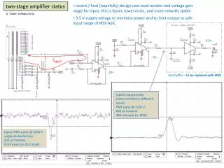
Input pulse ECL output Transimpedance amplifier (TIA) Differential amplifier Comparator • Current-Feedback OPA • Low input impedance • High slew rate • Transimpedance gain, Gz=5kΩ • Voltage Gain=20V/V Latch/Hysteresis control Latch input O.C. gate Hysteresis current mirror Currently, the threshold is set by potentiometer on the prototype card. +/-5V DC power supply +5V DC power supply Duplicate to other 15 channels Figure 1. Block diagram of PreAmp-Discriminator Card
Circuit simulation with TINA-TI design software Transimpedance Amplifier Differential Voltage Amplifier Current generator (Current In) Differential voltage out • Input impedance : <140Ω • Transimpedance gain : 100KΩ • -3dB Bandwidth : ~60MHz • Wide linear Input current range : +/-25uA • Differential voltage output swing : +/-2.58V • ESD protection diodes and ECL comparator are not shown. The simulation result in plots shown in next two pages.
DC analysis AC analysis Small input current vs output voltage Small-signal sine-wave response Large input current vs output voltage Large-signal sine-wave response
AC transfer characteristic Noise analysis Input voltage noise density (without current-limited series resistor, 100Ω) Transimpedance gain vs. frequency Input current noise density (without current-limited series resistor, 100Ω) Input impedance vs. frequency (with current-limited series resistor, 100Ω)
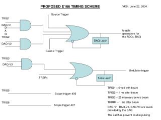
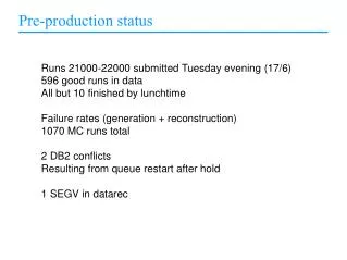
Sensitivity polarity Input signal Input polarity vs. ECL output. First use pulse generator as the input Agilent 33120A waveform generator, Tektronix TDS 754D Oscilloscope, +/-5.0V operation for PreAmp card
Input to PreAMP Amplified Signal Comparator Response
Input to PreAMP Amplified Signal Comparator Response
Amplifier / Discriminator Card • Current-feedback trans-impedance amplifier. • Low input impedance. • Voltage gain = 300. (can be changed in the final design.) • RMS of noise level~10mV. • S/N ratio improved after amplification
Dec 2008 • Complete schematic design of prototype CR module. • Set up a DAQ system using CODA in the lab. • Feb 2009 • Complete layout of prototype CR module. • Mar – May 2009 • Manufacture first 10 CR boards and test with DAQ readout. • R&D of 16-channel PD card prototype • June – Aug 2009 • Revise the design of CR for the final production if needed. • Produce the first 40 PD prototype cards. Test gain, rising time and investigate noise pick up. • Sep– Dec 2009 • Mass production of CR. Manufacture the rest 100 boards. Full system test. • Send PD prototype cards to test with MWPC chamber. Finalize design for the mass production. • Jan-March 2010 • Mass production of PD card. Manufacture the rest 60 cards. Testing. • April 2010 – Ship all CR and PD modules to Fermilab for final integration. • May 2010 – Aug 2010 – Install CR modules and PD cards.
Budget Request • ~150 K USD requested in a 3-year proposal for the construction of hardware from National Science Council of Taiwan • Waiting for approval in July 2009 and to be available starting from Aug 2009. (Chance of approval is high.) • Other source: AS Thematic Project. ~150K USD (less certain). Waiting for approval in summer 2009 and to be available starting from Jan 2010.
Points needed to be clarified before finalizing the design • CR Latch modules: • RF Latch signal input to CR: ECL or NIM? • RF signal works as system clock or latch trigger only? We will use higher frequency system clock in the latter case. • The connections between Trigger Supervisor in the master crate and Trigger Interface in our subsystem crates. Where the synchronizing of latch and level-2 trigger should be done? • ?
Points needed to be clarified before finalizing the design • PreAmp/Discriminator cards: • The RC-network on the detector side: interface between preamp and wire? • Power supply: from chamber side or externally equipped? • Geometrical size? • Voltage gain appropriate? • Threshold of comparator: 0-150 mV (enough?) • Realistic noise level? • Maximum pulse width from MWPC? (Signal tail pile up depending on the singles rate.) • Is the threshold adjustment via preferred? • 400 channels for prop tubes? • ?