Download
1 / 17
170 likes | 296 Vues
EU CRAFT PROJECT 016357. New method of video transfer and control functions for training in computer classroom and for audiovisual applications. WP4: User Interface. SCREENS – Tallin, 15 june 2006. Decisions. Solution A * as originally described: ARM9 + Linux

E N D
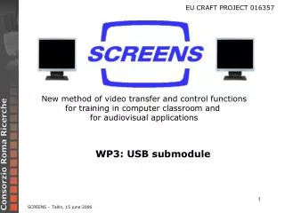
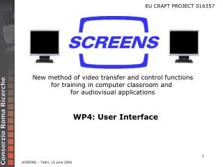
EU CRAFT PROJECT 016357 New method of video transfer and control functions for training in computer classroom and for audiovisual applications WP4: User Interface SCREENS – Tallin, 15 june 2006
Decisions Solution A * as originally described: ARM9 + Linux * several serial ports available * USB host port available * internal LCD controller Solution B: * BlackFin + uClinux * low cost versions have one serial port only * LCD may be driven with little glue logic * lower BOM * smaller physical size As agreed at the 3rd meeting in Braunschweig, march 16th 2006 (cfr. 3rd meeting minutes, 4.4 - WP4 progress) SCREENS – Tallin, 15 june 2006
User Interface block diagram buzzer Memory bus External Memory Interface ABCDEFGHIJKLMNOP Abcdefghijklmnopq 01234567890 SDRAM 64Mbit FLASH 32 Mbit LCD bias DISPLAY CS x 4 PLD Expansion connector UART line RS485 TIMER BF533 Vcore FET Parallel Peripheral Interface 3.3 VDC PLD 3.3 VDC LEDs on keyboard matrix KBD 5 VDC 12 VDC in To LCD SCREENS – Tallin, 15 june 2006
Architectural details, 1 • MATRIX KEYBOARD CONTROLLER • Whenever a keypress is detected, the PLD automatically generates a PPI access to the processor • Separate pins from the memory bus • Programmable speed directly from processor • scanning is zero-overhead • Clock source: internal timer/counter of the processor • 8-bit data: 5-bit column (single-bit), 3-bit row (encoded) • 32 keys are scanned, hw provisions for key debounce • 4 LEDs are controlled via programmable flags (ALL, GRP A, GRP B, DATAPROJECTOR) 1 bit active at time TIMER BF533 COLUMNS ROWS Parallel Peripheral Interface 4 COLUMNS PLD 8 ROWS LEDs on keyboard matrix KBD SCREENS – Tallin, 15 june 2006
Keyboard layout Updated keyboard layout and LED arrangement Cfr.: D1b: User Interface Specification, ver. 0.5 (05/05/2006) SCREENS – Tallin, 15 june 2006
Architectural details, 2 • MEMORY MAPPING • Due to limited address range of processor chip select lines, a simple PLD is required to allow access to all memory-mapped resources. • NOR FLASH: it contains bootloader and executable code in binary form • SDRAM: code is executed from here, at 133 MHz • LCD: 8-bit memory-mapped peripheral (two locations: control and data) • boot process: bootloader initializes SDRAM controller and copies data from FLASH into SDRAM Memory bus External Memory Interface ABCDEFGHIJKLMNOP Abcdefghijklmnopq 01234567890 SDRAM 64Mbit FLASH 32 Mbit LCD bias DISPLAY BF533 CS x 4 PLD SCREENS – Tallin, 15 june 2006
Architectural details, 3 SERIAL PORT The processor has a single UART, dedicated to the RS-485 interface along with a direction pin. EXPANSION CONNECTOR It contains the SPI port, for future expansion. buzzer UART line BF533 RS485 Expansion connector SCREENS – Tallin, 15 june 2006
SCREENS SW Emulator Windows-based software emulator of actions on User Interface, based on the D1b: User Interface Specification, ver. 0.3 (11/01/2006) D1b: User Interface Specification, ver. 0.5 (05/05/2006) SCREENS – Tallin, 15 june 2006
uClinux on Blackfin, 1 Recent trend: convergence of media processors and embedded operating systems Blackfin is a mixed architecture (DSP with RISC- and microcontroller-like extensions): MicroSignal Architecture (MSA) developed by Analog Devices and Intel uClinux is an operating system that is derived from the Linux kernel * intended for microcontrollers without Memory Management Units (MMU’s) • * available on many processor architectures, including the Blackfin processor Official repository, supported by Analog Devices http://blackfin.uclinux.org SCREENS – Tallin, 15 june 2006
uClinux on Blackfin, 2 Differences between Linux and uClinux 1. No real memory protection (a faulty process can bring the complete system down) 2. No fork system call 3. Only simple memory allocation 4. Some other minor differences Which is the advantage for SCREENS in using uClinux on Blackfin? * Low processor cost * Native Unicode handling * Availability of a file system * Easy retargetting on other platforms SCREENS – Tallin, 15 june 2006
Software development, 1 • STEP 1 • two applications on PC • GUI (TCP socket client) • core application (TCP socket server) screens_emulator.exe TCP socket server Configuration files LCD bitmap TCP socket client keystrokes SCREENS – Tallin, 15 june 2006
Software development, 2 • STEP 2 • one applications on PC • GUI (TCP socket client) • One application running on STAMP (BF533 board) • core application (TCP socket server) with configuration files • Communication thru LAN Configuration files screens_ctrl GUI on host TCP socket server LCD bitmap TCP socket client keystrokes SCREENS – Tallin, 15 june 2006
Software development, 3 • STEP 3 • Applications running on target board • core application with configuration files • keyboard management • RS-485 protocol • LCD driver • character generation • All look-and-feel issues are solved BEFORE implementation on target (consortium agreement on current version is required before proceeding with implementation on target) • the main application, based on configuration files, is already developed and debugged BEFORE implementation on target • The activites which must be scheduled on physical hardware are: SCREENS – Tallin, 15 june 2006
HW development • Status • HW specifications: completed • Components selection: completed • Schematics: completed. • PCB Layout: ready to start • PCB specs: • 4 layers, FR4, Dielectric constant Er 4.3 .. 4.5 • Gold or Silver finish -> RoHs and planarity • different solutions could be proposed by electro-Hill • 6 mils minimum trace • 6 mils clearance. • minimum via – DIA 0.5mm hole 0.3mm. • All vias filled with solder resist. SCREENS – Tallin, 15 june 2006
HW development • Next step • Agreement on schematics • Agreement on Bill of material • Start PCB Layout. • Prototypes (PCB, components procurement and assembly) fabrication: • by electro hill • to reduce final project cost • Production tuning now and not at the end of the PRJ • Only one step for production. • NRE only one time • CRR receive 2 assembled prototypes. • Start of debug and test SCREENS – Tallin, 15 june 2006
Status • SW Emulator: completed (except bugfixes), waiting for consortium agreeement • Schematics: completed • Layout: starts now (once approved) • Software: in progress • Bet version of firmware will be available 1 man-month after receiving a prototype SCREENS – Tallin, 15 june 2006
THANK YOU SCREENS – Tallin, 15 june 2006