Download
1 / 34
400 likes | 598 Vues
Explore the workings of pacemakers, including components, types, functions, and stimulation of cardiac tissue. Delve into unipolar and bipolar systems, pacing cycles, and more.

E N D
Basics of Pacemaker Functioning T K Govindarajan Medtronic
Topics • Components of a Pacemaker System • Types of Pacemakers & their Operation • Functions of a Pacemaker System • Stimulation of cardiac tissue • Sensing of intrinsic heartbeats • Single chamber timing cycle
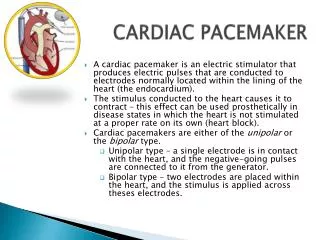
The Pacemaker System Cardiac Pacing is the artificial electrical stimulation of the heart in the absence of intrinsic heartbeats causing it to contract
A Unipolar Pacing System • Flows through the tip electrode (cathode) • Stimulates the heart • Returns through body fluid and tissue to the IPG (anode) Anode - Cathode
A Bipolar Pacing System • Flows through the tip electrode located at the end of the lead wire • Stimulates the heart • Returns to the ring electrode above the lead tip Anode Cathode Tip electrode coil Indifferent electrode coil
NBG Code Revised - 2002 I II III IV V Programmable Multi Site Chamber Chamber Response Paced Sensed to Sensing Functions/Rate Pacing Modulation V: Ventricle V: Ventricle T: Triggered V: Ventricle A: Atrium A: Atrium A: Atrium I: Inhibited D: Dual (A+V) D: Dual (T+I) D: Dual (A+V) D: Dual (A+V) O: None O: None O: None O: None R: Rate modulating S: Single (A or V) S: Single (A or V) O: None
Sense Pace Pace Single Chamber Pacemakers Ventricular Single Chamber Pacing or VVI pacing Pacing Rate Pacing Rate Pace
Rate Responsive Pacemakers Rate-Responsive Pacing Fixed-Rate Pacing Normal Heart Rate Running 150 Walking 100 Heart Rate (bpm) Wake-up Resting Sleeping Sitting 50 0 Daily Activities
Activity Sensors • Activity sensors employ a piezoelectric crystal that detects mechanical signals produced by movement • The crystal translates the mechanical signals into electrical signals that in turn increase the rate of the pacemaker Piezoelectric crystal
Pacing system - a standard electrical circuit The pacemaker provides the voltage.Current (electrons) flow down the conductor to the lead tip or cathode (-)Where the lead tip touches the myocardium, electrical resistance is produced. The current then flows through the body tissues to the anode (+) and back to the battery.All of the above are required for current to flow. I V R
Voltage, Current, and Impedance Voltage: The force moving the current (V) In pacemakers it is a function of the battery chemistry Current: The actual continuing volume of flow of electricity (I) This flow of electrons causes the myocardial cells to depolarize Impedance: The sum of all resistance to current flow (R) Impedance is a function of the characteristics of the conductor (wire), the electrode (tip), and the myocardium (tissue).
Ohm’s Law Describes the relationship between voltage, current, and resistance (impedance) V = I X R I = V / R R = V / I V I R V V I R I R V I R = X = =
Lead Impedance ValuesElectrical Analogies • Normal resistance – friction caused by the hose and nozzle Normal 300 – 1200 Ohms • Low resistance –leaks in the hose reduce the resistance Similar to a pacemaker lead with an insulation breach which results in low resistance and high current drain; may cause premature battery depletion. • High resistance – a knot results in low total current flow Similar to a pacemaker lead with a lead conductor break - impedance will be high with little or no current reaching the myocardium.
High Impedance ConditionsA Fractured Conductor A fractured wire can cause Impedance values to rise Current flow from the battery may be too low to be effective Impedance values may exceed 3,000 W Lead wire fracture Increased resistance Other reason for high impedance: Lead not seated properly in pacemaker header (usually an acute problem).
Insulation breaks can cause impedance values to fall Current drain is high and can lead to more rapid battery depletion Current can drain through the insulation break into the body or other lead wire, not through myocardium Impedance values may be less than 300 W Low Impedance ConditionsAn Insulation Break
Stimulation Threshold • Pacing Voltage Threshold • The minimum pacing voltage • at any given pulse width • required to consistently stimulate the heart • outside the myocardial refractory period causing it to contract
Capture – Loss of Capture Capture Non-Capture VVI / 60
The Pacemaker Stimulus 2.5 Volts 0.5 ms Voltage 1 sec Time Pacing Stimulus Voltage or Amplitude – 2.5 Volts Pulse Width – 0.0005 seconds or 0.5 milliseconds Pacing Rate – One stimulus per second or 60 stimuli(beats) perminute
2.0 1.5 1.0 .50 .25 The Voltage-Strength Duration Curve • Stimulus Voltage & Pulse Width have an exponential relationship • At short pulse widths (<0.25 ms) the curve rises sharply • At long pulse widths (>1.0 ms) the curve is flat Stimulation Threshold (Volts) Capture 0.25 1.0 1.5 Duration Pulse Width (ms)
The Pacing Pulse V = Pulse Amplitude in Volts (V) (say 2.5 V) t = Pulse Duration or Width in milliseconds (ms) (say 0.5 ms) R = Impedance of Pacing Circuit (ohms) (say 500 ohms) I = V/R = Current through pacing circuit (mA) = 2.5 V/ 500 ohms = 0.005 A = 5 mA E = Energy delivered by Pulse to the Pacing Circuit and Cardiac Tissue = V . I . t = I2Rt = V2t/R = 2.5 V . 5 mA . 0.5 ms = 6.25 micro Joules If V = 5 V Energy = 25 micro Joules t Pacing Pulse V Output Voltage t Pulse Duration (Width)
Why measure stimulation threshold? • To enable programming stimulus voltage amplitude and pulse width such that • Consistent capture & Patient Safety is ensured • Battery drain minimized, Pacemaker longevity maximized • Good thresholds • Ventricle - <1V @ 0.5ms • Atrium - <1.5V @ 0.5ms
Evolution of Pacing Threshold 6 s Safety Margin 4 VoltageThreshold (V) 3 2 Chronic Phase 1 Acute Phase 0 4 8 12 16 Observation Time (weeks)
Depolarization Wave Processed by Device Sensing of intrinsic heartbeats • Sensing is the ability of the pacemaker to “see” when an intrinsic depolarization is occurring • Pacemakers record the Intracardiac Electrogram (EGM) by constantly recording the potential difference between the cathode and anode
Intrinsic R wave Amplitude • Intrinsic R wave amplitude 5 mV • Intrinsic P wave amplitude 2 mV Intrinsic R wave in EGM Amplitude The Intrinsic R wave amplitude is usually much greater than the T wave amplitude
Sensitivity Setting 5.0 5.0 2.5 2.5 Amplitude (mV) Amplitude (mV) 1.25 1.25 Time Time Sensitivity settings less than 2.5 mv – High sensitivity – can lead to oversensing Sensitivity settings greater than 2.5 mV – Low sensitivity – can lead to undersensing
Undersensing . . . • Pacemaker does not “see” the intrinsic beat, and therefore does not respond appropriately Scheduled pace delivered Intrinsic beat not sensed VVI / 60
Oversensing • An electrical signal other than the intended P or R wave is detected • Pacing is inhibited Marker channel shows intrinsic activity... ...though no activity is present
VP VP Refractory & Blanking Periods • Refractory period • Prevent lower rate timer reset due to oversensing • Blanking Period • The first portion of every refractory period • Pacemaker is “blind” to any activity and no events can be sensed • Designed to prevent oversensing of pacing stimulus & after-potential Lower Rate Interval VVI / 60 Blanking Period Refractory Period
Values to remember • Pacing Thresholds • Atrium - <1.5V; Ventricle <1V @ 0.5ms PW • Outputs • 2 X threshold Voltage • Doubling Voltage output = 4 X Energy drain from battery • P / R wave amplitudes • P Wave > 2mV • R Wave > 5mV • Sensitivity • R / P wave > 2 X Sensitivity setting • Oversensing – Increase sensitivity ( Reduce value) • Undersensing – Reduce sensitivity ( Increase value) • Lead impedance • 300 – 1200 ohms – Normal • > 3000 Ohms - lead fracture / Loose set screw / inadequate lead pin insertion • < 300 Ohms – Insulation break • If impedance is out of range – try unipolar configuration
Dual Chamber Pacemakers Advanced type of pacemakers that closely mimic the natural heart Work on both – RA and RV Usually 2 leads Maintain AV Synchrony AV Interval Provide rate response
Dual Chamber Pacemakers • DDD, DDDR – sense & pace both atrium and ventricle • VDD – Sense atrium, pace ventricle
The four faces of dual chamber pacing AV SEQUENTIAL PACING Atrial Pacing Rate – 60, AV Interval – 200 ms AV Synchronous Pacing :NATURAL ATRIAL CONTRACTION & VENTRICULAR PACING : VDD AV Interval = 150 ms Spontaneous Atrial Rate – 55 Spontaneous Atrial Rate – 110
The four faces of dual chamber pacing Atrial Pacing Rate = 70, Natural AV conduction NATURAL ATRIAL CONTRACTION WITH NORMAL AV CONDUCTION Spontanoeus Atrial Rate = 65, Spontaneous PR interval = 160 ms