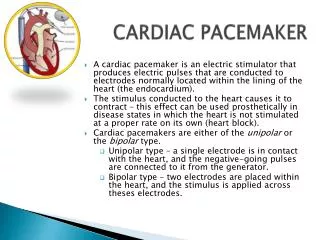
PACEMAKER BASICS
PACEMAKER BASICS. Frijo jose a. Anode. Cathode. Cathode: negative Electrode on the tip of a pacing lead Anode: positive The “ring” electrode on a bipolar lead The PG case on a unipolar system. Implantable Pacemaker Circuit. Pulse generator (PG): Battery Circuitry Connector(s)


PACEMAKER BASICS
E N D
Presentation Transcript
PACEMAKER BASICS Frijojose a
Anode Cathode • Cathode: negative • Electrode on the tip of a pacing lead • Anode: positive • The “ring” electrode on a bipolar lead • The PG case on a unipolar system
Implantable Pacemaker Circuit • Pulse generator (PG): • Battery • Circuitry • Connector(s) • Leads • Cathode • Anode • Body tissue Lead IPG Anode Cathode
The Pulse Generator • Battery - provide energy • Circuitry - controls pacemaker operations • Connector- join the PG to the lead(s) Connector Block Circuitry Battery
Lead Characterization • Position within the heart • Endocardial/transvenous leads • Epicardial leads • Fixation mechanism • Active/Screw-in • Passive/Tined • Shape • Straight • J-shaped used in the atrium • Polarity • Unipolar • Bipolar • Insulator • Silicone • Polyurethane
Endocardial Passive Fixation Leads • The tines become lodged in the trabeculae,a fibrous meshwork, of the heart Tines
Transvenous Active Fixation Leads • The helix, or screw, extends into the endocardial tissue • Allows for lead positioning anywhere in the heart’s chamber • The helix is extended using an included tool
Epicardial Leads • Leads applied directly to the surface of the heart • Fixation mechanisms include: • Epicardial stab-in • Myocardial screw-in • Suture-on • Applied via sternotomy or laproscopy
Unipolar lead Lead Polarity • Unipolar leads • Smaller diameter lead body than bipolar leads • Usually larger pacing artifacts on ECG • Bipolar leads • Usually less susceptible to oversensing of non-cardiac signals To tip (cathode) Bipolar coaxial lead
Unipolar Pacing System • Lead has only one electrode –cathode – at the tip • PG can - anode • When pacing, the impulse: • Flows through the tip electrode (cathode) • Stimulates the heart • Returns through body fluid and tissue to PG can (anode) Anode + • more interference (myopotentials) • Big spike on ECG • Pectoral (pocket) stimulation possible Cathode -
Bipolar Pacing System • The lead has both an anode and cathode • The pacing impulse: • Flows through the tip electrode located at the end of the lead wire • Stimulates the heart • Returns to the ring electrode, the anode, above the lead tip Anode + Cathode - Anode • less interference • Spike difficult to see on ECG • No pectoral (pocket) stimulation Cathode
STIMULATION THRESHOLD • The minimum stimulus intensity & duration necessary to reliably initiate a propagated depolarisingwavefront from an electrode • For a pacing stimulus to “capture”, the stimulus must exceed a critical amplitude & must be applied for a sufficient duration • Stimulus amplitude & duration interact- minimal amplitude required to capture depends on the pulse duration
Strength–Duration Relation Stimulus amplitude for endocardial stimulation has an exponential relation to duration of the pulse- rapidly rising strength–duration curve at pulse durations <0.25 ms and a relatively flat curve at pulse durations > 1.0 ms
Chronaxie pulse duration ~ point of min threshold energy on strength–duration curve • With pulse durations > chronaxie- relatively little ↓ in threshold V • Wider pulse dur→wasting of energy without providing a substantial ↑ in safety margin • When threshold determined by ↓ amplitude, stimulus V set twice the threshold value • PG that determine threshold by automatically ↓pulse duration-at least 3times threshold • Wedensky effect
Hyperacute phase of threshold evolution- active fixation electrodes may produce,immediately following implantation,an ↑ stimulation threshold that ↓over the next 20-30 min- transient high threshold – a/c injury at myocardial–electrode interface
Proper programming of the stimulus amplitude • The strength–duration relation must be appreciated • The safety margin that is chosen for a particular pt must be based on the degree of pacemaker dependency • An appreciation of the effect of stimulus amplitude & duration on battery longevity • The overall metabolic & pharmacologic history of the pt must be considered • Pacing threshold varies inversely with surface area of the stimulating electrode
Strength–Interval Relation • The stimulation threshold is influenced by the coupling interval of electrical stimuli and frequency of stimulation • ICD- greater stimulus intensity during ATP than during antibradycardia pacing
(Ztotal) = ZcZeZp Zp - related to movmnt of charged ionmyo toward the s in cathode Zp -directly related to pulse duration & can be ↓ by use of relatively ↓ pulse durations Polarization is inversely related to SA of electrode- to ↓ Zp but ↑ Ze, SA of electrode can be made large but radius small by use of a porous coating
Afterpotential of opposite chargeis induced in the myocardium at the interface of the stimulating electrode
The slope of intrinsic deflectn (dV/dt) expressed in V/s -referred to as slew rate For an EKG to be sensed, the amplitude & slew rate must exceed the sensing threshold
For a battery,the decay characteristics should be predictable. The ideal battery should have a predictable fall in V near the end of life, yet provide sufficient service life after initial voltage decay to allow time for the elective replacement indicator to be detected and for replacement to be performed
RATE-ADAPTIVE SENSORS • Activity Sensors and Accelerometers • Minute Ventilation Sensors
P- Native atrial depolarization • A- Atrial paced event • R- Native ventricular depolarization • V- Ventricular paced event • AV- Sequential pacing in the atrium and ventricle • AVI- Programmed AV pacing interval • AR- Atrial paced event foll by intrinsic ventricular • ARP- Atrial refractory period • PV- Native atrial foll by paced ventricular, P-synchronous • AEI- Interval from a ventricular sensed/paced to atrial paced event, the VA interval
NASPE/ BPEG Generic (NBG) Pacemaker Code I. Chamber II. Chamber III. Response to IV. Programmability V. Antitachy Paced Sensed Sensing Rate Modulation arrhythmia funct. O= none O= none O= none O= none O= none A=atrium A= atrium T= triggered P= simple P= pacing V= ventricle V= ventricle I= inhibited M= multi S= shock D= dual D= dual D= dual C= communication D= dual (A+V) (A+V) (T+I) R= Rate Modulation Manufacturers’ Designation only: S= single S= single (A or V) (A or V)
AOO & VOO • By application of magnet • Useful in diagnosing pacemaker dysfunction • During surgery to prevent interference from electrocautery
Ventricular asynchronous (VOO) pacing • Neither sensing nor mode of response • Irrespective of any other events, V pacing artifacts occur at programmed rate. Timing cycle cannot be reset by any intrinsic event
Atrial asynchronous (AOO)AV sequential asynchronous (DOO) • AVI & VAI or AEI are both fixed- intervals never change, as is insensitive to any atrial or ventricular activity, and timers never reset
Ventricular demand inhibited (VVI) • Sensing on V channel- output inhibited by sensed V event • Refractory after V/R- VRP- any V event in VRP-not sensed & doesn’t reset V timer • LRL
VVI MODE • Automatic interval starts from a paced complex (to the next paced complex) • Escape interval starts from a sensed complex (to the next paced complex) Automatic Interval • If the intervals are equal: • No hysteresis • If the escape interval > automatic interval: • Hysteresis Escape Interval
VVI MODE (with hysteresis) 1000 ms 850 ms Escape interval = 1000 ms (60 ppm) Automatic interval = 850 ms (70 ppm)
AAI • Useful for SSS with N- AV conduction • Should be capable of 1:1 AV to rates 120-140 b/m • Atrial tachyarrhythmias should not be present • Atria should not be “silent” • If no A activity, atria paced at LOWER RATE limit (LR) • If A activity occurs before LR,- “resetting” • An A activity too early may not cause depolarisation& better not sensed- ARP • Caution- far-field sensing of V activity
Single-Chamber Triggered-Mode • Output pulse every time a native event sensed • ↑current drain • Deforms native signal • Prevent inappropriate inhibition from oversensing when pt does not have a stable native escape rhythm • Can be used for noninvasive EPS,with already implanted PPI tracking chest wall stimuli created by a programmable stimulator
AV sequential-V Inhibited Pacing (DVI) • PPI is inhibited & reset by sensed V activity but ignores all intrinsic A complexes • Native R during AVI sensed – V output inhibited & AEI reset • For both A&V stimuli to be inhibited, sensed R must occur during AEI
AV Sequential, Non–P-Synchronous Pacing with D-Chamber Sensing (DDI) • AAI + VVI • Difference btw DVI & DDI- DDI incorporates A sensing as well as V sensing- prevents competitive A pacing • Mode of response is inhibition only- no tracking of P waves - paced V rate cannot be > programmed LRL • Goes by LR for each • Timing cycles- LRL, AVI, PVARP & VRP
A Synchronous (P-Tracking) Pacing (VDD) • VAT + VVI • Timing cycle- LRL,AVI,PVARP,VRP,& URL • Concept of AV interval (AVI) • A sensed atrial event initiates AVI • Goes by LR • If no A event occurs, PPI escapes with a V pace at LRL- VVI • AV block with intact sinus node function (esp useful in congenital AV block)
DDD • VAT + AAI + VVI • AV interval & VA interval • VA interval replaces the LR • Concept of PVARP (to prevent endless loop or PMT) • Indications • 1. The combination of AV block and SSS • 2. Patients with LV dysfunction & LV hypertrophy who need coordination of atrial & ventricular contractions to maintain adequate CO
A P V P A P V P DDD ExamplesThe Four Faces of DDD • Atrial and ventricular pacing • Atrial pace re-starts the lower rate timer andtriggers an AV delay timer (PAV) • The PAV expires without being inhibited by a ventricular sense, resulting in a ventricular pace
A P V S A P V S DDD ExamplesThe Four Faces of DDD • Atrial pacing and ventricular sensing • Atrial pace restarts the lower rate timer and triggers an AV delay timer (PAV) • Before the PAV can expire, it is inhibited by an intrinsic ventricular event (R-wave)
A S V P A S V P DDD ExamplesThe Four Faces of DDD • Atrial sensing, ventricular pacing • The intrinsic atrial event (P-wave) inhibits the lower rate timer and triggers an AV delay timer (SAV) • The SAV expires without being inhibited by an intrinsic ventricular event, resulting in a ventricular pace