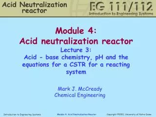
Acid Neutralization Reactor
Acid Neutralization Reactor. Module 4: Acid neutralization reactor Lecture 2: Analysis of the feed tank and the reactor for the case of no reaction. Mark J. McCready Chemical Engineering. Outline for today. Quick review of mass balance equations

Acid Neutralization Reactor
E N D
Presentation Transcript
Acid Neutralization Reactor Module 4: Acid neutralization reactor Lecture 2: Analysis of the feed tank and the reactor for the case of no reaction Mark J. McCready Chemical Engineering
Outline for today • Quick review of mass balance equations • Analysis of the reactor for 2 feeds but no reaction • Expectation of a Steady State ... • Analysis of the feed tank that is draining by gravity • How does the depth of liquid affect the flow rate? • Bernoulli equation to relate effects of gravity, pressure and velocity within a fluid
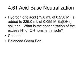
Reactor, what will the exit concentration be? Acid in, 1 Control volume Base in, 2 3 Flow out, 3
Feed Tank, how fast does it drain? We will use this control volume for the tank h
Start of new material • First we will analyze the reactor using the mass balance equations. • Today, there will be no reaction. • But, we will allow for inlet streams of different concentration. • We will see that if the inlet concentrations and flows are constant, a steady - state is expected where there is no change in the concentration with time in the tank.
Today, we will not do reaction,just use the tank as a mixer Control volume Salt solution in, 1 Another salt solution in, 2 3 Flow out, 3
Recall Mass Balance • General mass balance equation for a fixed control volume • Rate of Accumulation = • Rate In - Rate Out + Production by reaction- • Consumption by reaction • Overall • Component mass (mole) balance • r j- density of stream j, (mass/length3) • qj -- volumetric flow rate of stream j, (length3 /time) • V -- active volume of reactor,(length3) • cji-- molar concentration of species i in stream j, (moles/length3) • ri -- molar reaction rate per volume (moles/(length3 -time))
Today, we will not do reaction,just use the tank as a mixer Salt solution in, 1 Control volume Another salt solution in, 2 Flow out, 3
Mass Balance 1 A sketch of our problem looks like: 2 3 • We see two inputs and one output • Overall mass balance • Component mass balance, for salt • qj -- volumetric flow rate of stream j (m3/s) • V -- active volume of reactor (m3) • cjsalt-- molar concentration of salt in stream j (moles/m3) 3 The reaction term is 0!!
Simplifications • Flowrates in are not changing in time • Reactor is filled at the beginning • Thus, overall mass balance tells us nothing we don’t find obvious. • What about the salt balance? We expect that it will tell us what comes out, if we know what goes in.
Balance equation • The salt balance equation# • Can be solved to give… • You can solve this equation by numerical integration #A green background slide means that we don’t expect you to get the answer, because we used mathematics you may not yet understand. But, the answer will be insightful.
Plot of the concentration Initial concentration =0 • We see that there is an initial transient (exponential) that depends on reactor volume and then a steady state is reached after which there is no further time variation. (If the inlets remain constant!) • Steady state answer: Note different volumes and abscissa scales Initial concentration =0
Steady state concentration • For this example we have • q1 = 10 m3/s, c1 = 2 moles/ m3 • q2 = 5 m3/s, c2 = 3 moles/m3 • Thus: • q3 = (10 + 5)= 15 m3/s Note different volumes and abscissa scales
Steady state behavior? • Is there always a steady state if we have steady inputs to a reactor? • Maybe this is obvious ?? • Should we have even bothered to integrate? • Think of some examples….
Feed Tank, how fast does it drain? Now let’s examine a feed tank We need a new control volume This tank has an exit stream, but no inlet streams. h
Draining tank A sketch of our problem looks like: Control valve • We have just one output • Overall mass balance: since we can use the chain rule to get But…, how do we get u3? h u3,A3 area of exit pipe, velocity of fluid leaving in stream 3. we know the flowrate and velocity are related by thus
Draining tank Factors that affect exit liquid flowrate • ATank --not really • h-- yup! • A3-- yes, consider a 4”pipe versus a hypodermic needle • How open the valve is (as denoted by K) • g, gravity -- well of course • can’t drain a tank on the space station with gravity! Control valve, K h h=0 u3,A3 area and velocity
Pressure-depth relation • Common occurrence in the summer • Basic equation of hydrostatics: Wow,my ears hurt r =density g=gravitation constant P=pressure h=depth of liquid
Effect of depth • So we expect that if the depth is greater, the flow rate will be faster • Can we quantify this? • Recall from Physics, • Consider conversion ofpotential to kinetic energy for a fluid blob. • First we take the case of no “friction” or drag
KE--PE relation,we get velocity • Consider a blob of fluid in our tank. It will follow the path shown with no friction Control valve, K h a m g h = PE h=0 u3,A3 area and velocity h DKE+ DPE = 0 1/2 m (ub2 -ua2 )+mg (hb-ha) = 0 ub2 = 2 g Dh h=0 b KE = 1/2 m u2
Draining tank with control valve • We see that the velocity will not depend on the area of exit pipe. • Now for the real system we have a control valve that can open and close, the easiest way to deal with this is to consider that it causes a “loss” of energy. • DKE + DPE + “losses” = 0 • 1/2 m (ub2 -ua2 )+mg(hb-ha) + K/2 ub2 = 0 • (1+K) ub2 = 2 g Dh As K increases, velocity decreases. As the valve is closed, K increases!
WHITE BOARD STUFF • Notre Dame law of wind direction • How momentum of fluid is converted to an increase in pressure as it impinges on a wall? • Student--University paradox • How the pressure must increase if the fluid is to be slowed down. • Work--Energy Principle from Physics • Bernoulli Equation
Bernoulli equation • The relation between the pressure, the velocity, the change in height and frictional losses: • For our draining tank, there is no pressure change, and the relation between u and h is • Now we can go back to the mass balance and finish solving the problem
Draining tank Recall the mass balance • You can solve this numerically to find how h changes in time. Control valve, K We use our relation, note that the “b” subscript is now “3” h h=0 u3,A3 area and velocity To get a final equation that can be solved ...
Draining tank This one has a rather ugly analytical solution… h(t)= Here is a plot of some results K varies from 0 to 12 K=12 K=0
Filling/draining tank (for homework) 2 1 • What do the equations for this tank look like? • This last equation can be easily solved numerically to get height versus time. Substitute for the unknown flow rate and the liquid depth 3 3 Now use the Bernoulli equation
Recap (mixing tank) 1 2 3 • Component mass balance for “mixing tank” • The behavior is: Steady-state answer
Recap (draining tank) Control valve, K • Overall mass balance for draining tank u3,A3 area and velocity K varies from 0 to 12
RecapBernoulli equation • Bernoulli equation • Useful engineering equation to describe large-scale fluid flows. It relates changes in pressure, height and velocity and accounts for frictional losses.