Download
1 / 39
390 likes | 876 Vues
Explore the phenomenon of induced electric fields due to changing magnetic flux through surfaces, calculation of induced electric field strength, and application of Kirchhoff's Loop Rules in DC circuits. Learn about resistors, voltage, current, power, and circuit components.

E N D
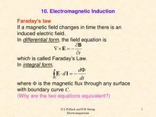
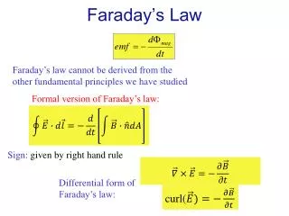
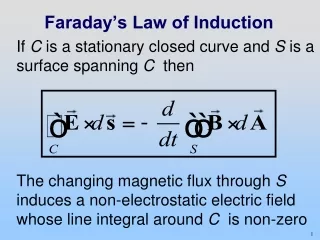
Faraday’s Law of Induction If C is a stationary closed curve and S is a surface spanning C then The changing magnetic flux through S induces a non-electrostatic electric field whose line integral around C is non-zero
Problem: Calculating Induced Electric Field Consider a uniform magnetic field which points into the page and is confined to a circular region with radius R. Suppose the magnitude increases with time, i.e. dB/dt > 0. Find the magnitude and direction of the induced electric field in the regions (i) r < R, and (ii) r > R. (iii) Plot the magnitude of the electric field as a function r.
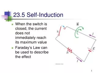
W10D2DC Circuits Today’s Reading Assignment W10D2 DC Circuits & Kirchhoff’s Loop Rules Course Notes: Sections 7.1-7.5 3
PS 8 due Week 11 Tuesday at 9 pm in boxes outside 32-082 or 26-152 Next Reading Assignment W10D3 PS07: PhET: Building a Circuit 7.1-7.5, 7.10 Exam 3 Thursday April 18 7:30 pm –9:30 pm Announcements
Outline DC Circuits Kirchoff’s Laws Electrical Power Measuring Voltage and Current
Electromotive Force (EMF) The work per unit charge around a closed path done is called electromotive force EMF. This is a bad name because it is not a force. Let denote the force per unit charge, then the EMF is If a conducting closed path is present then
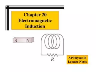
Ideal Battery • Inside Battery: chemical force non-zero inside battery (zero outside) moves charges through a region in which static electric field opposes motion • 2) Ideal battery: net force on charges is zero • 3) Potential difference between its terminals • 4) Extend path through external circuit where
Sign Conventions - Battery Moving from the negative to positive terminal of a battery increases your potential
Sign Conventions - Resistor Moving across a resistor in the direction of current decreases your potential
Internal Resistance Real batteries have an internal resistance,r, which is small but non-zero Terminal voltage: (Even if you short the leads you don’t get infinite current)
Series vs. Parallel Series Parallel
Resistors In Series The same current I must flow through both resistors
Resistors In Parallel Voltage drop across the resistors must be the same
Measuring Potential Difference A voltmeter must be hooked in parallel across the element you want to measure the potential difference across Voltmeters have a very large resistance, so that they don’t affect the circuit too much
Measuring Current An ammeter must be hooked in series with the element you want to measure the current through Ammeters have a very low resistance, so that they don’t affect the circuit too much
Measuring Resistance An ohmmeter must be hooked in parallel across the element you want to measure the resistance of Here we are measuring R1 Ohmmeters apply a voltage and measure the current that flows. They typically won’t work if the resistor is powered (connected to a battery)
Concept Question: Bulbs & Batteries An ideal battery is hooked to a light bulb with wires. A second identical light bulb is connected in parallel to the first light bulb. After the second light bulb is connected, the current from the battery compared to when only one bulb was connected. • Is Higher • Is Lower • Is The Same • Don’t know
Concept Question: Bulbs & Batteries An ideal battery is hooked to a light bulb with wires. A second identical light bulb is connected in series with the first light bulb. After the second light bulb is connected, the current from the battery compared to when only one bulb was connected. • Is Higher • Is Lower • Is The Same
Electrical Power Power is change in energy per unit time So power to move current through circuit elements:
Power - Battery Moving from the negative to positive terminal of a battery increases your potential. If current flows in that direction the battery supplies power I
Power – Resistor (Joule Heating) Moving across a resistor in the direction of current decreases your potential. Resistors alwaysdissipate power
Concept Question: Power An ideal battery is hooked to a light bulb with wires. A second identical light bulb is connected in parallel to the first light bulb. After the second light bulb is connected, the power output from the battery (compared to when only one bulb was connected) • Is four times higher • Is twice as high • Is the same • Is half as much • Is ¼ as much
Concept Question: Power An ideal battery is hooked to a light bulb with wires. A second identical light bulb is connected in series with the first light bulb. After the second light bulb is connected, the light (power) from the first bulb (compared to when only one bulb was connected) • Is four times higher • Is twice as high • Is the same • Is half as much • Is ¼ as much
Current Conservation Sum of currents entering any junction in a circuit must equal sum of currents leaving that junction.
Concept Question: Measuring Current If R1 > R2, compare the currents measured by the three ammeters: • A1 > A2 > A3 • A2 > A1 > A3 • A3 > A1 > A2 • A3 > A2 > A1 • A3 > A1 = A2 • None of the above • Not enough information is given.
Sum of Potential Differences Around a Closed Path Sum of potential differences across all elements around any closed circuit loop must be zero.
Sum of Potential Differences Around a Closed Path Sum of potential differences across all elements around any closed circuit loop must be zero.
Demonstration:Five Different Types of Resistance F13 http://tsgphysics.mit.edu/front/?page=demo.php&letnum=F 13&show=0
Steps of Solving Circuit Problem 1. Straighten out circuit (make squares) 2. Simplify resistors in series/parallel 3. Assign current loops (arbitrary) 4. Write loop equations (1 per loop) 5. Solve
Worked Example: Circuit What is current through each branch of the circuit shown in the figure below?
Worked Example: Simple Circuit Current conservation at a: Lower Loop: Start at a and circulate clockwise. Then Upper Loop: Start at a and circulate clockwise. Then Solve for I2: and
Four resistors are connected to a battery as shown in the figure. The current in the battery is I, the battery emf is ε, and the resistor values are R1 = R, R2 = 2R, R3 = 4R, R4 = 3R. Determine the current in each resistor in terms of I. Group Problem: Four Resistors
Demonstration:Wheatstone Bridge F14 http://tsgphysics.mit.edu/front/?page=demo.php&letnum=F 14&show=0
Group Problem: Wheatstone Bridge A circuit consisting of two resistors with R1=6.0 ohms and R2=1.5 ohms, a variable resistor, with resistance Rvar, a resistor of unknown value Ru, and 9.0 volt battery, are connected as shown in the figure. When Rvaris adjusted to 12 ohms, there is zero current through the ammeter. What is the unknown resistance Ru?