Download

1 / 16
160 likes | 269 Vues
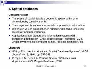
Spatial Databases - Topology. Spring, 2007 Ki-Joune Li. Spaghetti Model. The Most Simple Representation by Vector Model Point Table Line Table. P1 (30,70). L1. P4 (20,60). L5. L4. L3. P3 (20,50). P2 (40,50). L2. Spaghetti Model. Example: DXF

E N D
Spatial Databases- Topology Spring, 2007 Ki-Joune Li
Spaghetti Model • The Most Simple Representation by Vector Model • Point Table Line Table P1 (30,70) L1 P4 (20,60) L5 L4 L3 P3 (20,50) P2 (40,50) L2
Spaghetti Model • Example: DXF • A CAD Data Format by Spaghetti Model • Representation of geometric properties not spatial or geographic ones • Program Assignment #1 • Decode given data file in DXF • Define schema of Oracle spatial DB • Insert objects into DB • Programming Environment: JDBC + Oracle SDO • Due data: by April 23th
Problem of Spaghetti Model: Example • When P1 moves to (40,80), Ambiguity P1 (40,80) P1 (30,70) L4 L1 P4 (20,60) L5 ? L3 40, 80 P3 (20,50) P2 (40,50) L2 40, 80
P5 (30,70) P1 (40,80) L4 P4 (20,60) L1 L5 L3 P3 (20,50) P2 (40,50) L2 Problem of Spaghetti Model: Example • To make it clear • Relationship betweenPoint and Line 40, 80 No change of line table
Problem of Spaghetti Model: Example • No clear information about the connection without additional data • L1:L3 ? or L1:L2 P2 L1 : 3,300V L2 : 220V P1 P3 P5 L4 : 220V L3 : 3,300V P4 Need Topological Information
l1 l2 l3 l1 l2 l3 l4 l5 l5 l4 Topology • Topology • Invariant properties during elastic transformation (rubber sheeting) • Relationship between Spatial Objects • Topological Equivalence (Homeomorphism)
Some Definitions of Topology • Mathematical Definition based on Point Set Theory • An area: Defined as an infinite set of points • Neighbor of p: set of all points within a unit disc of p • Boundary: Set of all points that have neighbors within A and neighbors within AC at the same time • Interior and Exterior Neighbor of p p Boundary of A neighbors in A, neighborsin AC AC A
B A B A B B A A, B Examples of Topologies B A Disjoint(A,B) Meet(A,B) Overlap(A,B) A Some complicated cases ? Cover(A,B) or CoveredBy(B,A) Contain(A,B) or Inside(B,A) Equal(A,B) A 8 Relationships B Topology between Lines ?
A B Representation of Topology by 9-IM • 9-Intersection Model • Example • Extensions of 9-IM R(A,B)= R(A,B)=
Built-In Topology: Topology Levels • By VPF (Vector Product Format): A Military Standard • VPF NATO Standard CEN/TC287 ISO/TC211 • Level 0: No topology (Spaghetti Model) • Level 1 • Level 2 • Level 3: Face topology Less Topology More Topology
p3 p2 p1 l2 l3 l1 Topology Level 1: Connectivity • Description of connectivity between lines • l1 is connected with l2. • Example • Pipeline network • No Planarity restriction
Topology Level 2: Connectivity + Planarity • Topology Level 1 + Planarity Condition • Planarity • Only ONE object at a position • No overlapping is allowed • Example: ? p3 p3 p2 l21 l12 p2 l11 p5 l1 p1 p1 l2 l22 p4 p4 Level 2 Level 1 (not Level 2)
B B A A C C B A C Topology Level 3: Face Topology • Topology Level 2 + Face Topology • Adjacency between faces • Left / Right Face of a line • Example Original Boundary With Face Topology Without Face Topology
How to maintain the Planarity of Faces • Example 1 • Example 2 Original Faces F2 New Face to respect the planarity F1 F3 F2 F1 New Inserted Line
Point (Node) • (X,Y) • Line (Edge) • Point String Face Simple Data Modeling of Topology Starting Pt 1..1 Connected Line 1..* Ending Pt 1..1 Connected Line 1..* Topology Level 1, 2 Left Face 1..1 Right Face 1..1 Boundary 1..* Boundary 1..* Topology Level 3 • Face with Holes ? Outer Ring Inner Ring