Specific Combinational Functions
n. Decoders convert n-bit words to m 2. unique outputs. Encoders perform inverse operation of decoder. Multiplexers select one of many inputs to a single output. Demultiplexers performs inverse operation of multiplexer. min or max terms. structurally identical to decoder.

Specific Combinational Functions
E N D
Presentation Transcript
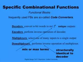
n Decoders convert n-bit words to m 2 unique outputs Encoders perform inverse operation of decoder. Multiplexers select one of many inputs to a single output Demultiplexers performs inverse operation of multiplexer. min or max terms structurally identical to decoder Specific Combinational Functions Functional Blocks frequently used FBs are so-called Code Converters. Digital design Ed F. Deprettere Leiden University
Recall, A decoder is a circuit that has n inputs and m 2n outputs Terminology: 2-to-4 line decoder, 3-to-8 line decoder, … Outputs are minterms (or maxterms) of the inputs Example: 2-input decoder. Inputs: A1, A0. Outputs: D3, D2, D1, D0 Decoders m0 Digital design Ed F. Deprettere Leiden University
Again, decoders are basic blocks. We use them over and over again – as we shall see. A0 D0 A1 D1 D2 E D3 enable bit: all D zero whenever E is zero Decoder is basic block You’ll find this symbol in library Digital design Ed F. Deprettere Leiden University
0 1 0 0 0 0 0 0 0 0 2-to-4 1 0 0 1 Enable bit Design enable bit instructs decoder when it is to be active all outputs are zero if enable bit is zero Truth Table Example: D0 = (A0 + A1 + E')' = A0 ' A1 'E = m0•E Digital design Ed F. Deprettere Leiden University
A = A’B’ D 0 I0 I1 I2 I3 B = A’B D 1 Y =AB’ D 2 = AB D 3 E E A B Y 1 0 0 I0 1 0 1 I1 1 1 0 I2 1 1 1 I3 Y(A,B,I0,I1,I2,I3) = A’B’I0 + A’BI1 + AB’I2 + ABI3 I0 = 0 , I1 = I2 = 1 A + B (I3 =1) ; XOR(A,B) (I3=0) 2-variable functions Digital design Ed F. Deprettere Leiden University
As we know, the full adder has Three inputs: two bits to be added and a carry-in Two outputs: sum and carry out Logic Functions S(X, Y, Z) = ∑m(1,2,4,7) C(X, Y, Z) = ∑m(3,5,6,7) Idea: Decoder offers all minterms. So: OR minterms in S and C from decoder. Full adder with decoder Digital design Ed F. Deprettere Leiden University
Given: 2-to-4 decoders Required: 3-to-8 decoder Solution: each decoder realizes half the minterms. Enable selects which decoder is active: Bigger decoders from small once A2 = 0: enable top decoder A2= 1: enable bottom decoder Digital design Ed F. Deprettere Leiden University
k k A 2 n ROM stores 2 words of n bits each in a nonvolatile way. k It consists of 1) a k-to-2 decoder and 2) a programmable OR array 0 1 2 . . . 31 0 1 2 3 4 5-to-32 decoder 7 6 5 4 3 2 1 0 To be considered as having 32 inputs Each decoder out connected to one of the inputs of each OR gate 32 lines = 32 inputs/OR, 8 ORs 32 8=256 programmable connections. Read-only Memory (ROM) Address in Data out Digital design Ed F. Deprettere Leiden University
Address NXTADD1 NXTADD0 SEL DATAPATH 000 001 000 01 0000 IDLE INIT IDLE GO NONE 001 000 010 00 0101 010 011 100 10 0000 011 000 100 00 0010 100 010 000 11 1100 Three bits three bits three bits two bits four bits 12 bits 0 1 2 3 4 x x 3-to-8 decoder ROM design Is a Truth table Digital design Ed F. Deprettere Leiden University
Input Output (square of input) A2 A1 A0 B5 B4 B3 B2 B1 B0 0 0 0 0 0 0 0 0 0 0 0 1 0 0 0 0 0 1 0 1 0 0 0 0 1 0 0 0 1 1 0 0 1 0 0 0 1 0 0 0 1 0 0 0 0 1 0 1 0 1 0 1 0 1 1 1 0 1 0 0 1 0 0 1 1 1 1 1 0 0 0 1 B0 B1 B2 B3 B4 B5 0 A0 A1 A2 8X4 ROM Functions with ROM B0 = A0 B1 = 0 Digital design Ed F. Deprettere Leiden University
Recall: encoder is inverse operation of decoder. From minterms to binary It has 2n inputs Dk, and n outputs Al. the n outputs form together the binary code of the one input that is 1 Truth Table of 4-to-2 Encoder is a minterm (D3 m3) table! Encoders Consider a base-4 number (B3B2B1B0)4. To convert to binary, start with B0. If B0 = N (0, 1, 2 or 3), set DN to 1 and all other Dk to zero. Output is binary N. D2 = 1 What should happen when two inputs are 1? Undefined! Not very useful Digital design Ed F. Deprettere Leiden University
If there are k inputs, then the code has ( log2k ) outputs plus a validity bit V.V = 1 only if one or more inputs are1. If V=0, then result is invalid Else, only the left-most 1 in the input row will be “seen” by the encoder. Truth Table: 4-to-2 Priority Encoder Priority Encoder This is a condensed truth table corresponding to 16-row table. If you understand it, then you really understand don’t cares Digital design Ed F. Deprettere Leiden University
Recall: a multiplexer selects one from many inputs. It is a very usefull circuit. • It has • nselectinputs: S0 ... Sn-1 • 2ndata inputs: D0 ... • 1 enableinput E • One output Y • If E = 0, Y= 0 • Else, Y = Dk, where k =(Sn-1Sn-2 …S0) Multiplexer Digital design Ed F. Deprettere Leiden University
4-to-1 Multiplexer "Truth Table" select enableoutput Actual truth table has 27 = 128 rows D0, …,D3 ; S0, S1; and E Digital design Ed F. Deprettere Leiden University
S S 0 1 2 3 4 X 1 MUX 0 1 X0 X1 Y X2 X3 = E.D3S1S2 X0 = E AND D0S1S0 X1 = E AND D1S1S0 X2 = E AND D2S1S0 4x1 MUX The four underlined terms remind me of a decoder! Digital design Ed F. Deprettere Leiden University
Circuit Diagram System Diagram 2-input –bit bus A bus is a communication path to which several units have access, not at the same time. An arbiter is regulating the traffic. If two data words ASK for the bus, only one get it. All A (S=0) or all B (S=1) Digital design Ed F. Deprettere Leiden University
S1 S0 Y 0 0 D0 0 1 D1 1 0 D2 1 1 D3 4x1 MUX from 2x1 MUX'es Digital design Ed F. Deprettere Leiden University
n n selection inputs, and 2 data inputs – one for each minterm related to the selection inputs. Fine, but we can do with n-1 s-inputs! Implementing functions with MUX We already used decodersto implement functions. A MUX is essentially a decoder (with the mux’s external OR gate absorbed). Let’s implement F(X,Y,Z) = m(1,2,6,7) . X Y Z F 0 0 0 0 0 0 1 1 0 1 0 1 0 1 1 0 1 0 0 0 1 0 1 0 1 1 0 1 1 1 1 1 F is either Z, or Z, or 0, or 1 and (X,Y) is uniquely determining which one of these. So, take X and Y as the 2(!) selection bits, and Z, Z,0 and 1 as the 4 corresponding data bits. X = S1, Y = S0, Z = D0, Z = D1, 0 = D2, 1 = D3, F = Out Digital design Ed F. Deprettere Leiden University
En In Out • 0 x Hi-Z • 0 0 • 1 1 1 (high impedance: Out independent of In) In En Out In0 En0 OL In1 En1 Multiplexes Output Line (OL) Tri-state buffer (or driver) Digital design Ed F. Deprettere Leiden University
S 0 D0 D1 D2 D3 S 1 Y E Alternative Mux Digital design Ed F. Deprettere Leiden University
Input: a single data line D Output: 2 data lines D0, …, D(2 -1) n Operation: bring input to one of the outputs. Use n selection bits S0, …S(n-1) to determine which output line. S D 0 0 S 1 D 1 D 2 D 3 D The Demultiplexer Recall: a demultiplexer performs the inverse function of the MUX. D0 = (S0 + S1 + D')' = S0 ' S1 'D = m0•D Digital design Ed F. Deprettere Leiden University
Other Basic Blocks HALF ADDER X Y S C Z FULL ADDER Digital design Ed F. Deprettere Leiden University
n-bit Adder/Subtractor (ripple carry) Bn B1 B0 S An A1 A0 Co Cn Sn S1 S0 S(elector) = 0 B non-inverted 1 B inverted + C0 = 1 (2s complement) Digital design Ed F. Deprettere Leiden University
A + B + C0 (4-bit adder say) B = 0000, C0 = 1 increment by 1 B = 1111, C0 =0 decrement by 1 (in 2s complement) S = A’B’C + A’BC’ + AB’C’ + ABC = XOR(A,B,C) Ca = AB + C(XOR(A,B)) (use maps) If B=1, then S = XOR(A,C) Ca = A + C Increment and Decrement In such cases, the adder can be simplified. Example: Digital design Ed F. Deprettere Leiden University
Activation patterns for digits 0 through 9 The seven segments Example: BCD to Seven Segment Code Converter Input is BCD-code: Need four variables A, B, C, DOutputs are seven functions to drive LED segments a-g example A=0, B=1, C=0, D=1 denotes "5“ convert (ABCD) =0101 to (abcdefg) = 1011011 Digital design Ed F. Deprettere Leiden University
Truth Tables Digital design Ed F. Deprettere Leiden University
Synthesize Function 'a' EPI's:A'C, AAB'C'. Other PI's: B'C'D', A'BD C B A D Map for function 'a' a = A'C+A'BD+AB'C'+B'C'D' Digital design Ed F. Deprettere Leiden University
Verify Boolean Expression for 'a' Digital design Ed F. Deprettere Leiden University