Optics update
360 likes | 451 Vues
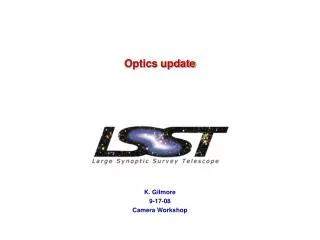
Optics update. K. Gilmore 9-17-08 Camera Workshop. Optical Design: Reference Design Parameters. Camera optical element prescription is established by V3 of the observatory optical design

Optics update
E N D
Presentation Transcript
Optics update K. Gilmore 9-17-08 Camera Workshop
Optical Design: Reference Design Parameters • Camera optical element prescription is established by V3 of the observatory optical design • Optical design of camera lenses and filters is integrated with optical design of telescope mirrors to optimize performance • 3 refractive lenses with clear aperture diameters of 1.55m, 1.02m and 0.70m • 6 interchangeable, broad-band, interference filters with clear aperture diameters of 0.76m • Why are transmissive optics required? • L3 required as vacuum barrier (6 cm thick) for focal plane cryostat • Filters required for science program • L1 & L2 required to minimize chromatic effect of L3 and filters • Baseline LSST optical design produces image quality with 80% encircled energy <0.3 arc-second Camera Optical Element Design Requirements
Optical Design: Reference Design Tolerances • Positioning and prescription tolerances of lenses and filters have been developed • The table below shows the rigid-body and prescription tolerances resulting from the tolerance analysis studies • The remaining tolerances that are yet to be defined are non-rigid body distortion limits and allowed relative deflections of elements this is being analyzed now Optical Element Positioning and Fabrication Tolerances
Prototype Optics Effort • 3.1 Optical Coatings • LSST camera optics require two distinct types of optical coatings: • 1. Anti-reflection (AR) coatings, • 2. Band-pass coatings. • The filters require both types of coatings while the lenses require only AR coatings. • Optical Coatings Proposal Schedule: • July 28, 2008 RFP Issued • Aug 04, 2008 All questions due • Sep 15, 2008 Proposal Submittal date • Oct 30, 2008 Anticipated Award date • Mar 30, 2010 Prototype contract deliverables sent to LSST (LLNL) for evaluation • Sep 1, 2010 Science Contract negotiations with vendors to begin
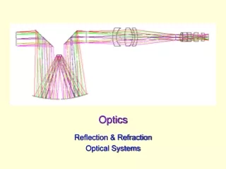
The camera optical design produces a flat focal plane Aspheric surface • LSST camera optical design includes, 3 large lenses and a set of 6 large transmission filters • Integrated design of lenses improves design • For example, adding asphericity to L2 simplifies testing and helps to reduce asphericity on secondary mirror
Filter band-pass is based on a combination of scientific considerations Specs • 75 cm dia. • Curved surface • Filter is concentric about the chief ray so that all portions of the filter see the same angle of incidence range, 14.2º to 23.6º Uniform deposition required at 1% level over entire filter Filter Band Pass Transitions
LSST Ideal Filters 100.0 80.0 60.0 Transmission u g r i z Y 40.0 20.0 0.0 300 400 500 600 700 800 900 1000 1100 1200 Wavelength (nm) Optical Design: Filter Reference Design • Filter band-pass characteristics are defined based on a combination of scientific considerations Filter Band Pass Transitions
LSST system spectral throughput in the six filter bands Includes sensor QE, atmospheric attenuation, optical transmission functions System throughput (%) Wavelength (nm)
Leak Update Orig Design Updated Design
OH Emission • Source - Bright airglow produced by a chemical reaction of hydrogen and ozone in the Earth’s upper atmosphere • Band system is due in part to emission from vibrationally excited OH radicals produced by surface interactions with ground-state oxygen atoms. • Emission can vary 10-20% over a 10 minute period • Ramsey and Mountain (1992) have reported measurements of the nonthermal emission of the hydroxyl radical and examined the temporal and spatial variability of the emission.
Ghost analysis shows worst case is double-reflection from thinnest spectral filter Double-reflection in filter Detector plane Ghost halo: 14 mm f Relative intensity of ghost image to primary image I = [ S / G]2 R1 R2 , S = image diameter = 0.020 mm G = ghost image diameter = 14 mm R = surface reflectivities = 0.01 I = 2.0 x 10 –10 = ~ 24 visual magnitude difference
By Num of Exposures n source type z Y1 Y2 Y3 25 elliptical-galaxy 1 2.09 1.81 2.19 50 elliptical-galaxy 1 2.95 2.56 3.10 75 elliptical-galaxy 1 3.61 3.13 3.79 100 elliptical-galaxy 1 4.17 3.62 4.38 125 elliptical-galaxy 1 4.66 4.04 4.89 150 elliptical-galaxy 1 5.11 4.43 5.36 175 elliptical-galaxy 1 5.52 4.78 5.79 200 elliptical-galaxy 1 5.90 5.11 6.19 225 elliptical-galaxy 1 6.26 5.42 6.57 250 elliptical-galaxy 1 6.60 5.72 6.92 275 elliptical-galaxy 1 6.92 6.00 7.26 300 elliptical-galaxy 1 7.22 6.26 7.58 325 elliptical-galaxy 1 7.52 6.52 7.89 350 elliptical-galaxy 1 7.80 6.77 8.19 375 elliptical-galaxy 1 8.08 7.00 8.48 400 elliptical-galaxy 1 8.34 7.23 8.75 S/N Calculations in Y-band By Seeing Seeing = 0.500 n source type z Y1 Y2 Y3 400 elliptical-galaxy 0 16.51 14.26 17.11 400 elliptical-galaxy 1 16.55 14.30 17.36 400 elliptical-galaxy 2 15.88 14.15 17.54 Seeing = 0.750 n source type z Y1 Y2 Y3 400 elliptical-galaxy 0 11.08 9.59 11.49 400 elliptical-galaxy 1 11.11 9.62 11.65 400 elliptical-galaxy 2 10.65 9.52 11.78 Seeing = 1.000 n source type z Y1 Y2 Y3 400 elliptical-galaxy 0 8.32 7.21 8.63 400 elliptical-galaxy 1 8.34 7.23 8.75 400 elliptical-galaxy 2 8.00 7.15 8.85 Seeing = 1.250 n source type z Y1 Y2 Y3 400 elliptical-galaxy 0 6.66 5.77 6.91 400 elliptical-galaxy 1 6.68 5.79 7.01 400 elliptical-galaxy 2 6.41 5.73 7.08 By Source n source type z Y1 Y2 Y3 400 elliptical-galaxy 0 8.32 7.21 8.63 400 elliptical-galaxy 1 8.34 7.23 8.75 400 elliptical-galaxy 2 8.00 7.15 8.85 400 spiral-galaxy 0 8.34 7.21 8.61 400 spiral-galaxy 1 7.74 7.30 7.75 400 spiral-galaxy 2 8.25 7.20 8.66 400 G5V 0 8.39 7.25 8.48 400 G5V 1 8.33 7.22 8.65 400 G5V 2 7.86 7.12 9.00
We have identified qualified vendors for the fabrication of large, thin, transmissive optics • Discussions initiated with multiple vendors • L3-Brashear • Goodrich • Tinsley • ITT • Substantial industrial base exists to fabricate large, thin optics • Industry estimates of cost and schedule to fabricate these large, thin optics have been used as input for LSST camera optics schedule and budget
Optics Fabrication • Corning manufacturing process for fused silica can produce glass of the required size and quality • Corning estimates of cost and schedule to produce the required fused silica glass have been used as input for LSST camera optics schedule and budget
We have identified qualified vendors for coating of large, thin, transmissive filters • Discussions initiated with multiple vendors • JDS Uniphase • Infinite Optics • SAGEM • Asahi Spectra • Substantial industrial base exists to coat large, thin filters • Industry estimates of cost and schedule to coat these large, thin optics have been used as input for LSST camera optics schedule and budget • These estimates include a risk reduction study during the R&D phase 120-inch coating chamber NOVA Laser Fusion Optics
Filter Procurement Process Design Study Define performance tradeoffs including shape coating designs, uniformity, repeatability Define possible parameters to relax without compromising science (Reduction in cost) Risk Reduction Study Engineering proof of concept. Required uniformity and spectral performance developed and tested Fabrication risks identified and addressed Create witness samples – Develop final cost/schedule estimates Production of Filters Create handling tools – AR coat filters
Vendor R & D Tasks • Establish procedures to distribute a uniform coating over the entire • filter surface. This includes evaluating several coating techniques • to determine best method of coating. • 2. Set-up test procedures to measure optical performance of filters. • 3. Determine optical quality of glass and coatings necessary for rejectingout-of-band transmissions. • 4. Develop techniques to ensure wavelengths of pass band edges are met. • 5. Establish ability to coat on two sides for spectral performance. • 6. Determine exact substrate thickness to achieve desired performancegoals. • 7. Monitor techniques to reduce variations.
Vendor R & D Tasks • Establish procedures to distribute a uniform coating over the entire • filter surface. This includes evaluating several coating techniques • to determine best method of coating. • 2. Set-up test procedures to measure optical performance of filters. • 3. Determine optical quality of glass and coatings necessary for rejectingout-of-band transmissions. • 4. Develop techniques to ensure wavelengths of pass band edges are met. • 5. Establish ability to coat on two sides for spectral performance. • 6. Determine exact substrate thickness to achieve desired performancegoals. • 7. Monitor techniques to reduce variations.
LMA IBS(Ion Beam Sputtering) deposition Facilities • Large IBS coater • 2,4 m X 2,4 m X 2,2 m inner deposition chamber • Designed to coat substrates up to 1 meter diameter • Used for VIRGO large mirrors since 2001 • Periodic quarter wave doublet stacks (Ta2O5 and SiO2) • Between 120 and 180 nm layer thickness Small IBS coater • Small IBS coater • Able to coat homogeneously up to 3“ substrates • Continual upgrades since 199 • Very flexible machine ideal for prototyping 350 mm diameter VIRGO mirrors Large IBS Coater
Thickness uniformity (%) Ta2O5 5 Iterative masking process (3 steps) Final uniformity :3.10-3over 700 mm 0 -5 -10 -15 C 01035 PC=50° C 01041 PC=50° Mask 1 -20 C 01043 PC=50° Mask 2 C 01047 PC=50° Mask 3 -25 -400 -300 -200 -100 0 100 200 300 400 Position (mm) LSST Filters uniformity • LSST filter shape (clear aperture of 750 mm and 12,5 mm of sagitta • use of Corrective mask technique To have the required uniformity • Previous LMA successfull works • Uniformity thickness control for large VIRGO mirrors • Gradient index profile on aspherical mirrors : diameter 550 mm and 120 mm sag
LSST filter design • The first optimizations with different materials show that the stack thickness needed for such filters is >> to 15 µm problem of stress and adhesion Optical stack for the R band (552 – 691 nm) optimized with TFCalc software at 18.9 ° (average angle of incidence) • • Solution : pass band = low-pass band + high-pass band • We coat the low band on one side of the filter substrate • We coat the high band on the other side
LSST filter design • R Pass band (552 nm -691 nm) optimization with tantala Ta2O5 and silica SiO2 • Edgeslopes = 1% < 5% • Out band transmittance = 0.01 % • In band transmittance = 99.75 % • More than 100 layers on each substrate side • Single layer thickness between few 10’s nm and few 100’s nm • Total thickness = 20 µm (>> 5 µm VIRGO mirrors) • No periodicity in the stack (not the case for VIRGO mirrors)
2,5" R Band test in the small IBS coater (july 2008) : Blue side • transmittance ~ 100 % OK • edge slope = 2,5 % OK • edge position : 20 nm redshift compare to the ideal R band filter • better control of the layer thickness needed • instability of the filament ion source, life time of the filament limited to 40 hours Spectrophotometer Data
R Band test in the small IBS coater (july 2008) : Blue side • out of band transmission : ~OK • Problem of the actual spectro-photometer sensitivity on going purchase of a new one Some 2,5“ test samples for the choice of a more sensitive spectrophotometer Spectrophotometer Data
Scheduled works in the small IBS coater • In the small IBS coater : • Replacement of the filament ion source by a more stable RF ion source • Test of new quartz for the QCM (Quartz crystal microbalance) more suitable for the thickness control of dielectric coatings • Continue coating R band filters on 1“substrates with new configuration (first try scheduled at end 2008)
Scheduled work in the Large IBS coater • In the large IBS coater : (waiting for financial support) • Faster shutter (screen hiding the substrate during the transition between two different layers) • Design conception : OK • Realisation and mounting in the coater : to be done • Increase substrate rotation speed : new motor • All this new equipment will boost the thickness control accuracy New faster shutter design Full size LSST filter (750mm dia.) Prototype filter Goal : Realisation of 4 R-band filter prototypes on squared silica substrates (around 100 mm by 100 mm)