Download
1 / 32
340 likes | 1.06k Vues
BLOCK DIAGRAM OF INTEL 8085. GURSHARAN SINGH TATLA professorgstatla@gmail.com. www.eazynotes.com. Introduction to 8085. Introduced in 1977. It is 8-bit MP. It is a 40 pin dual-in-line chip. It uses a single +5V supply for its operations. Its clock speed is about 3MHz. www.eazynotes.com.

E N D
BLOCK DIAGRAM OFINTEL 8085 GURSHARAN SINGH TATLA professorgstatla@gmail.com Gursharan Singh Tatla professorgstatla@gmail.com www.eazynotes.com
Introduction to 8085 • Introduced in 1977. • It is 8-bit MP. • It is a 40 pin dual-in-line chip. • It uses a single +5V supply for its operations. • Its clock speed is about 3MHz. Gursharan Singh Tatla professorgstatla@gmail.com www.eazynotes.com
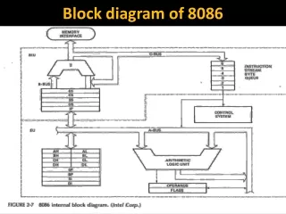
Block Diagram of 8085 Gursharan Singh Tatla professorgstatla@gmail.com www.eazynotes.com
Three Units of 8085 • Processing Unit • Instruction Unit • Storage and Interface Unit Gursharan Singh Tatla professorgstatla@gmail.com www.eazynotes.com
Processing Unit • Arithmetic and Logic Unit • Accumulator • Status Flags • Temporary Register Gursharan Singh Tatla professorgstatla@gmail.com www.eazynotes.com
Instruction Unit • Instruction Register • Instruction Decoder • Timing and Control Unit Gursharan Singh Tatla professorgstatla@gmail.com www.eazynotes.com
Storage and Interface Unit • General Purpose Registers • Stack Pointer • Program Counter • Increment/Decrement Register • Address Latch • Address/Data Latch Gursharan Singh Tatla professorgstatla@gmail.com www.eazynotes.com
Three Other Units • Interrupt Controller • Serial I/O Controller • Power Supply Gursharan Singh Tatla professorgstatla@gmail.com www.eazynotes.com
Accumulator • It the main register of microprocessor. • It is also called register ‘A’. • It is an 8-bit register. • It is used in the arithmetic and logic operations. • It always contains one of the operands on which arithmetic/logic has to be performed. • After the arithmetic/logic operation, the contents of accumulator are replaced by the result. Gursharan Singh Tatla professorgstatla@gmail.com www.eazynotes.com
Arithmetic & Logic Unit (ALU) • It performs various arithmetic and logic operations. • The data is available in accumulator and temporary/general purpose registers. • Arithmetic Operations: • Addition, Subtraction, Increment, Decrement etc. • Logic Operations: • AND, OR, X-OR, Complement etc. Gursharan Singh Tatla professorgstatla@gmail.com www.eazynotes.com
Temporary Register • It is an 8-bit register. • It is used to store temporary 8-bit operand from general purpose register. • It is also used to store intermediate results. Gursharan Singh Tatla professorgstatla@gmail.com www.eazynotes.com
Status Flags • Status Flags are set of flip-flops which are used to check the status of Accumulator after the operation is performed. Gursharan Singh Tatla professorgstatla@gmail.com www.eazynotes.com
Status Flags • S = Sign Flag • Z = Zero Flag • AC = Auxiliary Carry Flag • P = Parity Flag • CY = Carry Flag Gursharan Singh Tatla professorgstatla@gmail.com www.eazynotes.com
Status Flags • Sign Flag (S): • It tells the sign of result stored in Accumulator after the operation is performed. • If result is –ve, sign flag is set (1). • If result is +ve, sign flag is reset (0). Gursharan Singh Tatla professorgstatla@gmail.com www.eazynotes.com
Status Flags • Zero Flag (Z): • It tells whether the result stored in Accumulator is zero or not after the operation is performed. • If result is zero, zero flag is set (1). • If result is not zero, zero flag is reset (0). Gursharan Singh Tatla professorgstatla@gmail.com www.eazynotes.com
Status Flags • Auxiliary Carry Flag (AC): • It is used in BCD operations. • When there is carry in BCD addition, we add 0110 (6) to the result. • If there is carry in BCD addition, auxiliary carry is set (1). • If there is no carry, auxiliary carry is reset (0). Gursharan Singh Tatla professorgstatla@gmail.com www.eazynotes.com
Status Flags • Parity Flag (P): • It tells the parity of data stored in Accumulator. • If parity is even, parity flag is set (1). • If parity is odd, parity flag is reset (0). Gursharan Singh Tatla professorgstatla@gmail.com www.eazynotes.com
Program Status Word (PSW) • The contents of Accumulator and Status Flags clubbed together is known as Program Status Word (PSW). • It is a 16-bit word. Gursharan Singh Tatla professorgstatla@gmail.com www.eazynotes.com
Instruction Register • It is used to hold the current instruction which the microprocessor is about to execute. • It is an 8-bit register. Gursharan Singh Tatla professorgstatla@gmail.com www.eazynotes.com
Instruction Decoder • It interprets the instruction stored in instruction register. • It generates various machine cycles depending upon the instruction. • The machine cycles are then given to the Timing and Control Unit. Gursharan Singh Tatla professorgstatla@gmail.com www.eazynotes.com
Timing and Control Unit • It controls all the operations of microprocessor and peripheral devices. • Depending upon the machine cycles received from Instruction Decoder, it generates 12 control signals: • S0 and S1 (Status Signals). • ALE (Address Latch Enable). Gursharan Singh Tatla professorgstatla@gmail.com www.eazynotes.com
Timing and Control Unit • RD (Read, active low). • WR (Write, active low). • IO/M (Input-Output/Memory). • READY • RESET IN • RESET OUT • CLK OUT • HOLD and HLDA Gursharan Singh Tatla professorgstatla@gmail.com www.eazynotes.com
General Purpose Registers • There are 6 general purpose registers, namely B, C, D, E, H, L. • Each of the them is 8-bit register. • They are used to hold data and results. • To hold 16-bit data, combination of two 8-bit registers can be used. • This combination is known as Register Pair. • The valid register pairs are: • B – C, D – E, H – L. Gursharan Singh Tatla professorgstatla@gmail.com www.eazynotes.com
Program Counter • It is used to hold the address of next instruction to be executed. • It is a 16-bit register. • The microprocessor increments the value of Program Counter after the execution of the current instruction, so that, it always points to the next instruction. Gursharan Singh Tatla professorgstatla@gmail.com www.eazynotes.com
Stack Pointer • It holds the address of top most item in the stack. • It is also 16-bit register. • Any portion of memory can be used as stack. Gursharan Singh Tatla professorgstatla@gmail.com www.eazynotes.com
Increment/Decrement Register • This register is used to increment or decrement the value of Stack Pointer. • During PUSH operation, the value of Stack Pointer is incremented. • During POP operation, the value of Stack Pointer is decremented. Gursharan Singh Tatla professorgstatla@gmail.com www.eazynotes.com
Address Latch • It is group of 8 buffers. • The upper-byte of 16-bit address is stored in this latch. • And then it is made available to the peripheral devices. Gursharan Singh Tatla professorgstatla@gmail.com www.eazynotes.com
Address/Data Latch • The lower-byte of address and 8-bit of data are multiplexed. • It holds either lower-byte of address or 8-bits of data. • This is decided by ALE (Address Latch Enable) signal. • If ALE = 1 then • Address/Data Latch contains lower-byte of address. • If ALE = 0 then • It contains 8-bit data. Gursharan Singh Tatla professorgstatla@gmail.com www.eazynotes.com
Serial I/O Controller • It is used to convert serial data into parallel and parallel data into serial. • Microprocessor works with 8-bit parallel data. • Serial I/O devices works with serial transfer of data. • Therefore, this unit is the interface between microprocessor and serial I/O devices. Gursharan Singh Tatla professorgstatla@gmail.com www.eazynotes.com
Interrupt Controller • It is used to handle the interrupts. • There are 5 interrupt signals in 8085: • TRAP • RST 7.5 • RST 6.5 • RST 5.5 • INTR Gursharan Singh Tatla professorgstatla@gmail.com www.eazynotes.com
Interrupt Controller • Interrupt controller receives these interrupts according to their priority and applies them to the microprocessor. • There is one outgoing signal INTA which is called Interrupt Acknowledge. Gursharan Singh Tatla professorgstatla@gmail.com www.eazynotes.com
Power Supply • This unit provides +5V power supply to the microprocessor. • The microprocessor needs +5V power supply for its operation. Gursharan Singh Tatla professorgstatla@gmail.com www.eazynotes.com