Download
1 / 24
270 likes | 669 Vues
Review of Projections and Coordinate Systems. Referencing Data to Real Locations. Coordinate Systems Geographic vs. Projected. Geographic Coordinate Systems (GCS) Location measured from curved surface of the earth Measurement units latitude and longitude Degrees-minutes-seconds (DMS)

E N D
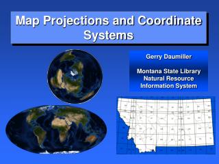
Review of Projections and Coordinate Systems Referencing Data to Real Locations
Coordinate SystemsGeographic vs. Projected • Geographic Coordinate Systems (GCS) • Location measured from curved surface of the earth • Measurement units latitude and longitude • Degrees-minutes-seconds (DMS) • Decimal degrees (DD) or radians (rad) • Projected Coordinate Systems (PCS) • Flat surface • Units can be in meters, feet, inches • Distortions will occur, except for very fine scale maps
Geographic Coordinate System • Parallels - east to west – 0° at the Equator (0 °-90 °) • Meridians – north to south – 0° at the Prime Meridian (0 °-180 °) • Latitude and longitude are angular measurements made from the center of the earth to a point on the surface of the earth
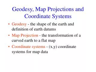
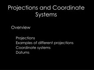
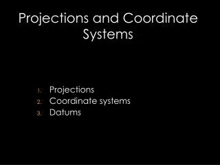
Map Projection: • A map projection is a mathematical formula for representing the curved surface of the earth on a flat map. • wide variety of projections possible • each projection will create a different type of distortion
Distortions • Distortions are inherent in maps • The Earth is round, a map is flat • distance • area • shape • direction
Datums A reference frame for locating points on Earth’s surface It consist of: • A spheroid (ellipsoid) with a spherical coordinate system and an origin. • A network of points that have been meticulously surveyed.
Modeling the Earth : spheroids, ellipsoid and datums! • North America Datums • NAD 27 • Clarke 1866 spheroids • Meades Ranch, KS • Local Datum • NAD 83 (National Geodetic Survey) • GRS80 (Geodetic Reference System) spheroid • Earth-centered • GPS compatible • WGS84 (National Imagery and Mapping Agency – National Geospatial – Intelligence Agency) • Additional parameters of model • Used in GPS Why all the trouble to learn about datums? 10- 100 meter shift between NAD 27 and NAD83/WGS 84!
Working with Coordinate Systems in ArcGIS • On-the-fly projection • “Define Projection” vs “Project” • Predefined Projections (provided by ArcGIS) • Projection File - .prj • Text file stores projection information • Data frame takes on the CS of the first data layer added to the project.
Map Projections Parameters • Standard Line – line of tangency - where the projection surface meets the globe • No distortion at this point – increase distortion moving away • Standard Parallel • Standard Meridian • More than one standard line possible • Central Line • Defines the center of the map projection • Central parallel - latitude of origin • Central meridian • Can be different from standard line • False Easting – x- coordinate value • False Northing – y- coordinate value 14
Commonly Used Map Projections in California • Universal Transverse Mercator (UTM) • California State System • (Teale) Albers Equal-Area Conic • State Plane Coordinate (SPC) System • Lambert conformal conic projection
Teale Albers Projection ( California) AKA: CA State System, CA Albers Equal Area Projection Surface: Conical Spatial Properties: Equal Area (Equivalent) Projection Parameter 1st Standard Parallel: 34° 00’ 00’’ 2nd Standard Parallel: 40° 30’ 00’’ Central Meridian: -120° 00’ 00’’ Central Parallel Latitude of origin: 00° 00’ 00’’ False easting (meters): 0 False northing (meters): -4,000,000 Example of Coordinate: X = -161,327 (meters) Y = -149,199 (meters)
Secant! 84 N° 80 S° Universal Transverse Mercator (UTM) • 60 zones • 6o wide • Defined by central meridian (example: 120° W) • Preserves direction and small shapes (conformal projection). • Extent is from 84°N to 80 °S. • UTM coordinates are easily recognized by 6 digit for the x, and 7 digit for the y ( most of the time at latitudes of 15° and greater in the Northern Hemisphere)
84 N° 80 S° UTM Zone 10 N and S Projection Surface: Cylindrical Spatial Properties: Conformal, Shape and Direction Projection Parameter False Easting: 500, 000m False Northing: 0 m Central Meridian: -123° Scale Factor: 0.999600 Example of Coordinate in Monterey: X = 602,585 (meters) Y = 4,050,086 (meters) Central Meridian Value Decrease Value Increase Value Increase False Easting 500,000 0m 0 m 10,000,000 m Equator Origin Value Increase 6°
UTM • Often found in military applications, and in datasets with global or national coverage • UTM system is secant with lines of scale 1 located on both sides of the central meridian, the projection is conformal, so small features appear with the correct shape and scale is the same in all directions. (Scale is 0.9996 at the central meridian and at most 1.0004 at the edges of the zones • Because there are effectively 60 different projections, maps will not fit together across a zone boundary.
State Plane Coordinate System (SPSC) • Although distortions of the UTM system are small, they are too great for accurate surveying • Plus zone boundaries follow arbitrary lines of longitude rather than jurisdictions. • Not a true map projection • Collection of different projections for every state in the US • Designed in the 1930s to provide a local reference system tied to a national datum. • Some states (depending on size and latitudinal extent) have multiple zones • Most USGS 7.5 minute maps indicate state plane coordinates (as well as UTM, and lat-long grid)
Cadastersand the US Public Land Survey System • The cadaster is defined as the map of land ownership in an area, maintained for the purposes of taxing land, or of creating a public record of ownership. • Parcels of land in a cadaster are often uniquely identified by number or by code.
The State Plane Coordinate System • East-West oriented States (or zones) use the Lambert Conformal Conic projection (ex. Tennesse) • North-South oriented States (or zones) use the Transverse Mercator projection (ex. Illinois) • One zone in Alaska uses Oblique Mercator • Based on the North American Datums: NAD27 and NAD83 • Reference is in Eastings and Northings
State Plane Coordinate System for California AKA: Lambert Conformal Conic Projection Surface: Conical Spatial Properties: Shape and Distance Projection Parameters False Easting: 6561666 False Northing: 1640416 Central Meridian: -119 ° Standard Parallel_1: 36.00 ° Standard Parallel_2: 37.25° Latitude Of Origin: 35.33 ° Example of Coordinate in Monterey: X = 5,798,378 (feet) Y = 2,135,524 (feet)