Download
1 / 30
320 likes | 553 Vues
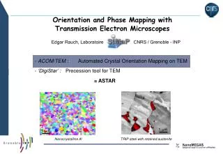
Orientation and Phase Mapping with Transmission Electron Microscopes Edgar Rauch, Laboratoire CNRS / Grenoble - INP - ACOM/TEM : Automated Crystal Orientation Mapping on TEM - ‘DigiStar’ : Precession tool for TEM = ASTAR. 1 m. 1 m. Nanocrystalline Al.

E N D
Orientation and Phase Mapping with • Transmission Electron Microscopes • Edgar Rauch, Laboratoire CNRS / Grenoble - INP - ACOM/TEM : Automated Crystal Orientation Mapping on TEM - ‘DigiStar’ : Precession tool for TEM = ASTAR 1 m 1 m Nanocrystalline Al TRIP steel with retained austenite
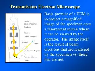
1) ACOM/TEM : Template matchingPattern acquisition and template generation 2) ASTAR : Combining orientation/phase identification with Electron Precession
0.5 m 1 µm ACOM/TEM : Automated Crystal Orientation Mapping WC-Co Severely deformed 7075 Al. Alloy Orientation map Phase map
1 µm ACOM/TEM : Automated Crystal Orientation Mapping Kikuchi pattern Orientation W + W’(= W +0.1°) Orientation W Severely deformed 7075 Al. Alloy Bragg Spot pattern
ACOM/TEM : Orientation Indexing Calculated diffraction pattern Diffraction pattern for arandomly oriented crystal orientation(j1,f,j2) Austenite, ferrite, one or two grains?
ACOM/TEM : Crystallographic orientation identification Pre-calculated templates Acquired pattern Stereographic projection (cubic ) • 111 • 001 101 • 1-11 Angular step size ~1° ~ 3000 templates orientation(j1,f,j2) Template Matching Rauch,E.F. & Dupuy,L. (2005). Arch. Metall. Mater. 50, 87–99. Correlation index
ACOM/TEM : Reliability Superimposed diffraction patterns at a grain bounday Templates for copper Stereographic projection Q2 Q1 Q1> Q2 R = 100 (1- Q2/Q1) Reliability
Deconvolution of superimposed Diffraction patterns reliability Fe - 60 ppmC severely deformed Bright field Orientation map Grain 1 Grain 2
ACOM/TEM : Phase identification and reliability Austenite : Index I2 = 389 Ferrite : Index I1= 553 PR = 100 (1- I2/I1) Phase reliability (= 30)
ACOM/TEM : four steps On line (hardware) TEMdpa.exe DiffGen.exe INDEX.exe Off line MapViewer.exe
TEMdpa : Diffraction Pattern Acquisition • Features: • up to 180 fps • easy selection of the area of interest • single or movie type DP acquisition • brightness, contrast, exposure time control • On line Virtual Bright Field construction
TEMdpa : Virtual Bright Field on-line construction Orientation map ‘ Bright field ‘
TEMdpa : Virtual Bright Field on-line construction Orientation map Virtual bright field image 1 m Bright field image Aluminium (mean grain size 200nm)
DiffGen : Template generator Features: Any crystallographic structure, any orientation Laue class related to the space group Structure generator (lattice, cell, structure factor)
DiffGen : Template generator Parameters that control the template file size Crystal symmetry Max angle (°) x1 x2 x3 x6 x6 x12 x2 x4 x4 x8 x24 err=1 a=3° a=3.8° Excitation error (a.u.) err=0.5
ACOM : some examples of orientation maps Orientation reliability Deformed Cu (coll. N. Llorca – Univ. Barcelona, Spain) Correlation Index Phase Reliability Orientations Fe 1.67% C(HT 10 min @ 1100°C, A. Stormvinter - KTH) AusteniteMartensite
300 nm 500 nm Grain sizeand Texture in 80 nm copper lines • CROSS VIEW (orientation map) • Grain size of the order of 30 nm may be identify despite the use of a conventional LaB6equipped Jeol 3010 TEM (spot size 25 nm). • A fiber texture was detected within the channel. 250x100 steps (13 nm each) LaB6 equipped Jeol 3010 TEM (spot size 25 nm) Scanning time : 10 min(44 fps) Side view 500x100 steps (6.5 nm each) , Spot size 25 nm Scanning time : 19 min (44 fps) 300x100 steps (6.5 nm each), spot size 15 nm Scanning time : 12 min (44 fps) SIDE VIEW (orientation and index superimposed map) The two scans were performed with different settings They demonstrated the reproducibility of the identification • Credits: • Stefan BRANDSTETTER, SIMaP - Grenoble INP
20 nm 20 nm ACOM/TEM combined to a FEG-TEM JEOL 2010F Texas Material Institute UT, Austin 180 nm Cu lines Virtual bright field Orientation map Correlation Index map Pt nanocrystals
1) ACOM/TEM : Template matchingPattern acquisition and template generation 2) ASTAR : Combining orientation/phase identification with Electron Precession
Precession Electron Diffraction patterns (R. Vincent, P.A. Midgley, Ultramicroscopy 53 (1994) 271.) SStar control of Deflection coils X: ½ Precession I: Standard setting Y: Full precession
Precession Electron Diffraction patterns Mayenite crystal (Ca12Al14O33) : space group I-43d Orientation Index Virtual Bright Field Without precession With precession precession angle : 0.35ºacquisition time 50 min (10 fps)
ACOM + Precession: Solving 180° orientation ambiguities B.c.c. Iron (ferrite), [112] I : Index=317, Reliability=0 Without precession Index Rotation angle (around the normal axis) With precession (1.5°) Index Diffraction patterns collected on a Philips CM120 (LaB6, 120 kV) Y : Index=670, Reliability=28
ACOM + Precession: Solving 180° orientation ambiguities Precession angle 0.5° Fe-1.5%Cu (annealed) [315] Orientation ambiguities [115]
Practice ASTAR (‘HRCOPM’) • TEM practice (acquisition) • PC practice (indexing and viewing)
Indexing Fourier transform of High resolution TEM images • Fast Fourier Transforms are performed on successive subsets of the high resolution image as if the sample was scanned. • The resulting patterns are compared to templates • Orientations and/or phases may be recognized • a small subset leads to higher spatial resolution • - larger subimages improve the indexing quality 6 nm 128 pixels = 3 nm FFT over 128x128 subimages FFT over 256x256 subimages 256 pixels = 6 nm • TITAN-Cubed : PbSe nanocrystals • Credits: • Marie CHEYNET, SIMaP - Grenoble INP • Odile ROBBE, LASIR – UTS Lille Orientation map (color) combined to INDEX (gray scale)
1 µm 1 µm ACOM : some examples of orientation maps Bright field images Nanocrystalline Al Deformed steel Severely deformed Cu Orientation maps
ACOM/TEM : Automated Crystal Orientation Mapping Fe 1.67% C (HT 10 min @ 1100°C, A. Stormvinter - KTH) Orientation map Phase map Austenite Martensite
Same area with (Y) and without (I) precession TRIP steel (ferrite + austenite) ; Philips CM120 @ 100hz (6 min), I Orientation Index reliability +phase Y