Download
1 / 76
1.07k likes | 2.07k Vues
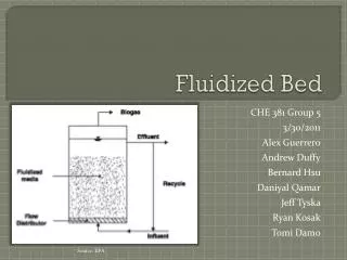
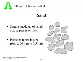
Fluidized-Sand Biofilters. Steven Summerfelt Freshwater Institute, Shepherdstown, WV Michael Timmons Cornell University, Ithaca, NY. Benefits of FSB. Treat dissolved wastes. Cost effective for large recycle systems: filter sand is relatively inexpensive,

E N D
Fluidized-Sand Biofilters Steven Summerfelt Freshwater Institute, Shepherdstown, WV Michael Timmons Cornell University, Ithaca, NY
Benefits of FSB • Treat dissolved wastes. • Cost effective for large recycle systems: • filter sand is relatively inexpensive, • cost for surface area is low ($0.02-0.001/m2) • biofilters scale to treat large flows • 1.5 – 15 m3/min • 400 to 4000 gal/min
FSB Can Be More Cost Effective • FSB are about 5 times less expensive than comparable trickling filters (Summerfelt & Wade, 1998, Recirc Today)
FSB Can Be More Cost Effective at Large Scales • Capital cost estimates associated with biofilter choice for a 1 million lb/yr tilapia farm. (Timmons et al., 2000)
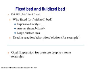
Fluidization Fundamentals • Buoyant force of rising water lifts sand bed when velocity exceeds minimum fluidization velocity (vmf).
Fluidization Fundamentals • Bed expansion terminology: • 50% expansion , e.g., 1 m of static sand depth expands to 1.5 m • 100% expansion , e.g., 1 m of static sand depth expands to 2.0 m • 200% expansion , e.g., 1 m of static sand depth expands to 3.0 m
Fluidization Fundamentals • Pressure drop across a sand bed • increases according to Ergun’s equation until bed begins to expand. • remains constant at all water velocities after the expansion begins. • remains constant for all sand sizes, • 1 m of static sand requires about 1 m of water head to expand. • see Summerfelt and Cleasby (1996) Bed height Pressure drop Superficial velocity
Fluidization Fundamentals • Estimate bed expansion for a given sand as a function of water velocity, using: • water viscosity and density • sand size, sphericity • void space of the static bed • see Summerfelt and Cleasby (1996) Bed height Pressure drop Superficial velocity
Applications: Coldwater vs. Warmwater lower fluidization velocities require larger beds than desirable lower TAN removal rates & efficiencies, biofloc management required cold-water systems: warm-water systems: super high fluidization velocities require beds to be too narrow and tall and limits TAN removal capacity without increasing flowrate thick biofilms, low velocities, biofloc manage- ment required, low loading rate, high removal %, TAN limiting, shallow beds, thin biofilms, high velocities, high loading rate, high removal rate, deep beds required, somewhat self cleaning effectiveness 0.0 0.2 0.4 0.6 0.8 1.0 1.2 Effective Diameter (D10), mm (See Timmons & Summerfelt, 1998)
Nitrification Rates • Warm-water & cold-water applications: (summarized by Timmons & Summerfelt, 1998)
Coldwater Applications • Fine sands (D10 = 0.20-0.25 mm) are used: • provide high specific surface areas • 11,000 m2/m3 • require low water velocities • 0.7-1.0 cm/s • provide longer hydraulic retention times across bed • 1-3 min
Coldwater Applications • Fine sands (D10 = 0.20-0.25 mm) are used: • produce higher TAN removal efficiencies • 80-95% TAN removal each pass • provide excess nitrification capacity • 200% excess can be achieved • controls nitrite-nitrogen at very low levels • generally < 0.1-0.2 mg/L
FSB Start-up in Coldwater Note 1. Step changes in make-up water flows were used to increase or decrease dilution when nitrite spiked. Note 2. Feeding reached 79 kg/day by 11/2/00 and TAN removal efficiency was > 50%. 3.00 • Start-up period at FI took 7-8 week at 14ºC. TAN 2.50 NO2-N 2.00 1.50 TAN and Nitrite-Nitrogen (mg/L) 1.00 0.50 0.00 8/7/00 9/4/00 8/14/00 8/21/00 8/28/00 9/11/00 9/18/00 9/25/00 10/2/00 10/9/00 10/16/00 10/23/00 10/30/00 Time (days)
FSB Performance in Coldwater • FSB first started up on ammonium chloride. Note 1. At stocking the fish density was 15 kg/m3 (mean fish weight = 150 g). Note 2. Last measured fish density was 33.5 kg/m3 (mean fish weight = 320 grams).
Biofilm Development • Biofilms develop around individual sand grains; Suggested reading: Nam et al. 2000. Aquacultural Engineering, 22: 213-224.
Biofilm Development in Fine Sand Biofilters Time • biofilms thicken with time: • decreasing particle density, • increasing bed expansion, • migrating to top of bed. Time
Biofilm Development in Fine Sand Biofilters shear shear • Shear forces tear biofilm pieces from the sand, shear shear shear shear
Biofilm in Fine Sand Biofilters • Water velocities (0.7-1.4 cm/s) do not flush larger sheared pieces from the bed; • such pieces accumulate & continue to grow.
Biofilm in Fine Sand Biofilters • biofilms grow on the expanded sand
Fine Sand Biofilters growth • Biofilter bed depth increases with time (about 8 cm/wk @ FI): • bio-particles accumulate; • bed expansion increases, • as thickening biofilm reduces particle densities.
Managing Bed Depth • Siphon biosolids from the bed: • maintain a maximum bed depth; • remove biosolids from the top, • removes thickest and oldest biofilm; • also remove some sand, • lost sand must be replaced on occasion.
Managing Bed Depth • Intermittent biosolids siphoning, • remove top 15-30 cm of bed, • only when bed reaches a max depth, • technique used in past. • Continuous biosolids siphoning: • 4-20 L/min (1-5 gpm) siphon rate, • 0.2 - 1% of total biofilter flow, • current tecchnique in FI’s growout system.
Managing Bed Depth • Siphoning biosolids from a biofilter in the Freshwater Institute’s old research system.
Managing Bed Depth • Siphon biosolids flow: • out of recirc system, • to recirc system drum filter. Filter inlet Filter outlet
Vertical Stratification • The beds are vertically stratified in: • sand size • bed expansion • biofilm thickness and biofloc size • nitrification rate
Vertical Stratification Particle Size 0.320 to 0.341 mm sand 4-15 m biofilm 0.9-1.1 mm biofloc Bio-particles 231-257% expanded Upper bed 0.343 to 0.358 mm sand 7-20 m biofilm 0.9-1.7 mm biofloc Bio-particles 203-207% expanded Middle bed 0.421 to 0.434 mm sand no visible biofilm no biofloc Scoured-sand 59-68% expanded Lower bed
Vertical Stratification Regional TAN Removal Rates (g/d/m2 sand surface) Upper bed Bio-particles 0.116 - 0.150 Middle bed 0.099 - 0.172 Bio-particles Lower bed Scoured-sand 0.031 - 0.048
Flow Distribution Mechanisms • Flow distribution methods vary, but are all important! 1-2 cm orifices distributed across false-floor (controlling P) orifices distributed across pipe-manifold (controlling P) slotted inlet about circumference (NO controlling P)
Distribution by Vertical Probes • In 1989, Dallas Weaver (Scientific Hatcheries) sold FI a FSB that used vertical injection probes. Freshwater Institute’s ‘old system’
Peterson Fish Farm (MN) Sierra Aquafarm (CA) Distribution by Vertical Probes (Designed by Dallas Weaver) (Designed by Dallas Weaver)
Distribution Through False Floor • Eric Swanson reported (Aqua Expo, 1992) flow injection underneath a false floor. false-floor distribution plate
Distribution Through False Floor • Buckmans Creek Hatchery (NB) fluidized- sand biofilter (Swanson-type design)
Distribution Through False Floor • Formerly Penobscot Smolt Hatchery (Franklin, ME) • Currently Center for Cooperative Aquaculture Research (Designed by Eric Swanson)
Distribution Through False Floor • Oak Bay Hatchery, Cooke Aquaculture (NB) (Swanson-type design)
Distribution Through False Floor • Atlantic Silver Hatchery (NB) (Designed by Eric Swanson)
Pipe-Lateral Distribution • Freshwater Institute adopted a modified pipe-lateral distribution manifold. swing check valve swing check valve outlet ball valve ball valve abrasion resistant floor
Pipe-Lateral Distribution • Modified pipe-lateral distribution manifold at Freshwater Institute’s old facility.
Pipe-Lateral Distribution • To create uniform flow distribution: • Pressure drop (P) across orifice should be headloss through the sand bed (i.e., depth of static sand): Qorif = flowrate in ft3/s Aorif= orifice area in ft2 C = 0.6 and g = 32.2 ft/s2
Pipe-Lateral Distribution • Glacier Springs Fish Farm (Manitoba) (system designed by FI)
Pipe-Lateral Distribution • Integrated Aquaculture Systems (PA) (system designed by FI)
Pipe-Lateral Distribution • Fingerlakes Aquaculture (NY) (farm designed by Mike Timmons)
Pipe-Lateral Distribution • Hunting Creek Fisheries (MD) (system designed by FI)
Pipe-Lateral Distribution • Bingham Hatchery (Maine) (system designed by PRAqua Tech.)
Pipe-Lateral Distribution • Target Marine Hatchery (BC) (systemdesigned by PRAqua Tech.) Courtesy of PRAqua Technologies (BC)
Pipe-Lateral Distribution • Target Marine Hatcheries(BC) (system designed by PRAqua Tech.)
Pipe-Lateral Distribution • Three salmon smolt systems at Nutreco’s Big Tree Creek Hatchery (BC) (system designed by PRAqua Tech.)
Patent protected technology from Marine Biotech Inc. (Beverly, MA) Cyclo Biofilter™
Water injected tangentially into circular plenum and through 1.9 cm (3/4”) slotted inlet about its base. Cyclo Biofilter™ slotted inlet
Cyclo Biofilter™ • Pressure drop across the piping, sand, & cyclo bio 0.4 psi 1.7 psi 6.4 psi sand P pipe & manifold P water lift (Freshwater Institute data)
Cyclo Biofilter™ Advantage • Cyclo Bio requires less pressure to operate. • 0.1-0.3 bar (2-4 psig) less pressure was required to operate a cyclo bio compared to a modified-pipe manifold FSB. • assuming a similar fluidized-sand biofilter height. • cyclo bio’s reduce P of piping and inlet orifice