Download

1 / 67
670 likes | 1.03k Vues
Get insights on the Schedule of Dimensions (SOD) by N.R. Kale, detailing track parameters, clearances, safety standards for Indian railways. Learn about the evolution, features, and importance of SOD in ensuring safe railway operations.

E N D
SCHEDULE OF DIMENSIONS PRESENTED BY N.R.KALE/Lecturer (works)
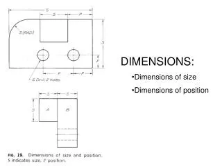
What is SOD ? • Schedule of dimension is nothing but a schedule, which lays down :- • Limiting values, recommended values, and infringement to limiting values, which can be continued over entire Indian railways system for various track parameters. • Goods wagon and coaching stock parameters. • Horizontal and vertical clearances to be followed on Indian railways.
Necessity of S O D • It is absolutely essential to ensure safety of traveling public as well as goods over entire Indian railways system. • To adopt uniform system of track tolerances, location of structures and construction standard all over the Indian railways. • To permit different types of coaching and goods stock owned by different railways to ply on entire railway system with same level of degree of safety.
Brief Introduction 1913 - First schedule of maxm & minm dimension. 1922 – SOD with Maxm. Minm & recommended dimension was published. 1929 – Amendment in order to introduce some improvement and additions of clearances required for electric traction. 1936 – Financial stringency on railway therefore amendment to restrict capital expenditure to minimum.
Contd. …. 1939 & 1958 reprinted with some modifications. 1973 – Reprinted with conversion to metric system, introduction of dimensions for 25KV AC traction. 1990 – Recommendations of 64th Track Standard Committee for revision of SOD of 1939 reprinted in 1973. 2004 – Revised version published with some modifications.
MAIN FEATURES OF SOD-2004 • Dimensions are given only for 1676 mm gauge. • Consists of only metric units. • Only two schedules – schedule I & schedule II • Extra clearances required for curves are modified to suit speed of 160 kmph and SE of 165 mm • Additional appendix for extra clearances required for 200 kmph is also given with 185 mm SE
SCHEDULE - I • Schedule I of SOD-2004 consists of those items which are mandatory and have to be observed on all 1676 mm gauge Railways in India. • Contains the items of Schedule- I and certain selected items of Schedule- II of 1973 Version
Contd. … DIMENSIONS given in Schedule-I are classified under two heads :- ‘Existing works’ – The works which were existing before issue of SOD ( 2004 ). ‘New works’ – Include new constructions, additions of new lines/structure, gauge conversion and doubling
Contd. … However following works will not be included in ‘New works’- Shifting of Points & Crossings. Extension of siding. Extension of building, etc.
SCHEDULE - II • Schedule – II contains the existing infringements of Schedule – I. • These are items, which were included in Schedule – III of 1973 version.
SCHEDULE I CHAPTER I • MIN. DIST. C/C OF TRACK . As per CS No.9 dated.16.10.2012 i) For existing works 4265 mm ii) For new works/additions to existing works 5300 mm Note: OHE mast and Signal post shall not preferably be provided in between tracks. However, under unavoidable circumstances, the clearance shall be increased by equal to width of such structure/foundation.
SCHEDULE I CHAPTER I • MIN. DIST. C/C OF TRACK (Tunnel, Semi-through/Through girder bridges) As per CS No.9 dated.16.10.2012 i) For existing works 4495 mm ii) For new works/additions to existing works 4725 mm
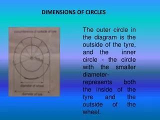
Contd. … • Minimum Radius of curves -175 m (10 degree) Note: Check rails to be provided in curves having radius 218 meters(8 degree) and sharper. Check rails may also be provided in flatter curves, if high speed is contemplated.
SCHEDULE I CHAPTER I CONTD… • Minimum clearance of check rail on curve. 44 mm. • Minimum clearance of check rail on level crossing. 51 mm. • Maximum clearance of check rail on level crossing. 57 mm • Minimum depth for wheel flange. 38 mm
Schedule I chapter I contd. … BULDING AND STRUCTURE Minimum horizontal distance from center of track to any structure from RL to 305 mm above RL • For existing works 1675 mm • For new works or alterations to existing works 1905 mm
Minimum horizontal distance from C/L of track to any structure except a platform.
Schedule I Chapter I contd. … Minimum horizontal distance of any telegraph post from C/L of nearest track • For existing works - Ht of the post + 2135 mm. • For new works - Ht of the post + 2360 mm.
Height of ROB & FOB (C.S.No.7/13) Min. ht. above rail level for a dist. Of 1600 mm on either side of the centre of track. Where 25 K.V. A.C. traction is likely to be used. F.O.B. 6250 mm (5270 mm)* R.O.B./ Fly over 5870 mm (5070 mm)* * For 4.80 M height of contact wire
C.S.No.10 Dated 08.11.12 Note for overhead structure- For existing overhead structures, wherever feasible, the ht. of contact wire shall be as high as possible to allow passage of ODC of 4.8 m height. If any T/out or X/over is within 40m or any LC is within 520m, the ht. shall be 6250m On lines proposed for electrified, provision shall be made in OHE structure to permit an allowance of 275mm for raising of track
Schedule I chapter I contd. … Safety Refuges :- Max. distance in tunnels 100 m On bridges with a)span less than 100 m 100 m b)spans of 100 m or more - On each pier
Schedule I chapter I contd. … Formation width :- (Considering formation slope of 1 in 30 and track distance 5300mm and straight track) For single line straight track – Min. width in embankment 6850 mm Min. width in cutting 6250 mm For Double line straight track – Min. width in embankment 12150 mm Min. width in cutting 11550 mm
Formation width as per CS No.16 of LWRM and CS No.135 of IRPWM
Schedule I chapter II(Station yard) Min. dist. Centre to centre of track :- (i) For existing works 4265 mm (ii) For new works / Alt. 5300 mm Max. gradient in Station yard :- (i) For existing works 1 in 400 (ii) For new works / Alt. 1 in 1200 Note: There must be no change of grades within 30 meters of any points & crossings.
The power of condonation for gradient steeper than 1 in 1200 in case of new work (As per Corrigendum to C.S. No.12)
Chapter ii contd. … Horizontal dist. From C/L of track to
Platform on curved track No passenger platform in case of new line, would be constructed on a curve having radius less than 875 M Extra allowance to be reduced by 51mm for platform, inside of curve. Extra allowance to be reduced by 25mm for platform, outside of curve.
Chapter ii contd. … Height above rail level –
Railway Board’s directives for Mumbai suburban section Vide letter No.2007/CEDO/SD/O dated 19.02.14, Railway Board has conveyed Board’s approval to change the height range of platform in Mumbai suburban section from 760-840mm to 840-920mm. RDSO has been asked to submit draft correction slip for Board’s approval which is yet to be issued.
Chapter II Contd.(Buildings and structures) Minimum Horizontal distance of any building on a passenger platform from center of track.
Contd. ….. (CS No. 11) • Min. horizontal distance of any bldg. or longitudinal boundary fence from centre line of track of passenger platform which is not an island (For New works) • Minimum 6830mm • Recommended 12130mm Note: Recommended dimension is for setting back the platform to make room for an additional track in future, without infringing minimum distance.
Chapter No. 2 contd. …. Minimum horizontal distance from center line of track to a pillar, column, lamp of similar isolated structure on a passenger platform.
CHAPTER II CONTD… POINTS & CROSSINGS :- Clearance of
Chapter ii contd. … Points & Crossings :-
Chapter ii contd. … Points & Crossings :-
SCHEDULE I CHAPTER IV (A) • Wheel Gauge 1599mm-1602mm. • Tread Dia of new wheel 914mm-1092mm. • Flange Projection 28.5mm-35.0 mm • Flange Thickness 16 mm- 29.4 mm* * As per CS No.14
Contd. … • Tyre width 127mm minimum. Floor height above RL • Passenger 1345mm-1220mm. • Goods 1345mm-1145mm. • Buffer height above RL 1030mm-1105mm • Maxim Wheel Base for 4-Wheeler - 6100mm