Sea-Force Presentation Outline
Sea-Force Presentation Outline. Conclusions. Introduction. Total Ship Evaluation. Requirements & Alternatives. Combat Systems. Hull. Logistics. Flight Deck. Propulsion. Electrical. TS3000, 3001, 3003. TS4002,4003. TS3002, 4000, 4001. TSSE Knowledge Scheme.

Sea-Force Presentation Outline
E N D
Presentation Transcript
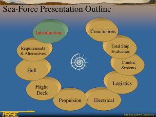
Sea-Force Presentation Outline Conclusions Introduction Total Ship Evaluation Requirements & Alternatives Combat Systems Hull Logistics Flight Deck Propulsion Electrical
TS3000, 3001, 3003 TS4002,4003 TS3002, 4000, 4001 TSSE Knowledge Scheme Capstone Design Project Realistic, Team-based Application TSSE Courses Systems Engineering Principles and Process Integration Processes and Techniques MS Degree (ME/Physics/ECE) — Foundation Engineering Understanding of Major Elements
LTJG Korkut Murat, Turkish Navy LT Koray Savur, Turkish Navy LT Matt Steeno, USN MAJ Chong-Ann Teh, RSN LT Dwight Warnock, USN 2002 TSSE Faculty and Team Members • Faculty Members • Professor Harney • Professor Papoulias • Team Members • LT Luis Alvarez, USN • LT Jihed Boulares, Tunisia Navy • MAJ Keng-Shin Chong, RSN • LT Lynn Fodrea, USN • LT Brian Higgins, USCG • LT Seth Miller, USN More information at www.nps.navy.mil/tsse/
Design Project Guidance …to examine the concepts associated with “seabasing”. and …produce a design for a ship to enable effective seabasing. and …explore the feasibility of building an LHA, MPF, and LMSR on a common hull form.
Option A Option B Option C Project Overview Review IRD Concept Exploration Conceptual Design 3 Ship Study Phase I Phase II Phase III
Design Constraints • Access to major U.S. ports. • Draft and height not greater than that of a CVN. • Length less than 1000 ft. • Displacement not greater than 100k LT • Technology ready for shipboard installation in 2020.
Sea Base 200 nm inland Chris Wagner Chris Wagner Chris Wagner Chris Wagner Chris Wagner Chris Wagner Chris Wagner Chris Wagner Chris Wagner Chris Wagner Chris Wagner Chris Wagner Chris Wagner 25 – 250 nm Re-supply route Pre-position base or friendly port outside of theater of operation
Sea-Force Presentation Outline Conclusions Introduction Total Ship Evaluation Requirements & Alternatives Combat Systems Hull Logistics Flight Deck Propulsion Electrical
Requirements Analysis • Systems Engineering and Analysis • Initial Requirements Document requests family of ships capable of Sea Basing and STOM • TSSE System Engineering Methodology • “Top Down” analysis of IRD • Traceability • Context • “Bottom Up” study of planned platforms • LHA(R), MPF(F), LMSR
Analysis of Alternatives • A. Single Ship Design • One hull form • Combat configured or logistics configured • B. LHA/MPF with LMSR • LHA/MPF variant – troops, hospital, combat systems • LMSR variant – fuel, provisions, ammo • C. MPF/LMSR with LHA • MPF/LMSR variant – troops, hospital, stores • LHA variant – combat systems
Sea-Force Presentation Outline Conclusions Introduction Total Ship Evaluation Requirements & Alternatives Combat Systems Hull Logistics Flight Deck Propulsion Electrical
What we needed in a hull design: • Large cargo capacity • Large flight deck • Space for a well deck • Durability/Survivability • Propulsion efficiency
Future sealift ship designs • Global Security.org • Nigel Gee and Associates Ltd.
HMS Triton • LOA…….312 ft • Beam……66 ft • Draft….10 ft • Displacement…..800 LT • Speed…..20 kts • Launched May 2000
Additional benefits from Tri Hull design • Wide open deck layouts • Excellent Stability • Protection from missile/Torpedo hits
Center Hull Characteristics • Length…..990 ft • Width……106 ft • Draft……..42 ft • Displacement…75,500 LT
Characteristics of main hull form • Flat transom to facilitate a well deck • Raised keel in stern to provide space for propulsors • High length-to-beam ratio • Wave piercing bow
Outrigger Hull Characteristics • Length…..550 ft • Width……20 ft • Draft……..32 ft • Displacement…6000 LT
Floodable length calculations • Led to location of watertight bulkheads and spaces
Structural calculations: Longitudinal stress • 10,050 psi……….maximum predicted stress • 15,000 psi………………..…allowable stress
Rolling calculations • Based on the same analysis done at MIT for the LHA-R design. • Predicted snap roll will be countered using anti-roll fins
Side well description • Rail system transfers vehicles / containers between Sea Force and LCUs.
Sea-Force Presentation Outline Conclusions Introduction Total Ship Evaluation Requirements & Alternatives Combat Systems Hull Logistics Flight Deck Propulsion Electrical
Flight Deck • Description • Aircraft • Minimize Manning
Flight Deck • Triple Tram Line • Length: 770 ft • Width: 300 ft • Area: 230,000 ft2 • 16 A/C spots • Centerline Runway • 3 A/C Elevators
Aircraft • 16 MV-22 • 4 Heavy Lift Aircraft • 6 JSF • 4 UH-1Y • 4 AH-1Z • 4 SH-60F
Manning Reduction • Technologies • Robotics • Omnidirectional Vehicles • Advance Weapons Elevator • Enhanced functions • Firefighting • Towing • Fueling • Aircraft loading
Sea-Force Presentation Outline Conclusions Introduction Total Ship Evaluation Requirements & Alternatives Combat Systems Hull Logistics Flight Deck Propulsion Electrical
Propulsion • Resistance Calculations and Power Req. • Alternatives for Propulsion Plant • Prime Mover Selection • Comparison of Gas Turbines • Propulsor Selection • Propulsion Motor Selection • Fuel Consumption comparison • Lay out plan
Alternatives for Propulsion Plant • Conventional steam plant • Nuclear steam plant • Diesel engines • Fuel cells • Gas turbines
Speed versus Power Diagram 24 Hour Ship Electric Load=>15 Mw (~20 000 Hp)
Prime Mover Selection • Gas turbine alternatives • Mt 30 TRENT • ICR w21 • LM1600 • LM2500 • LM2500(+) • LM6000 • Trade off Studies • LM1600 and LM2500(+) • LM2500(+) and LM6000 • Final Decision: 3 LM6000 and 1 LM2500(+)
Propulsor Choices • Water jets and hydro drive • Conventional propeller • Pods *The most feasible propulsor is electrical pods due to weight, volume, location flexibility and maneuverability.