Download
1 / 14
140 likes | 253 Vues
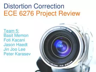
This document discusses advancements in geometrical distortion correction for the Advanced Camera for Surveys (ACS), presented by Richard Hook at the STScI TIPS Meeting on December 18, 2003. Key contributions include distortion terminations by the ACS Instrument Definition Team, local work on distortion coefficients, extensive calibration by Jay Anderson and Ivan King, and ongoing software support. The comparison between ACS and WFPC2 geometric distortion showcases ACS's improved stability over time, and the integration of advanced polynomial modeling significantly enhances data accuracy for astronomical observations.

E N D
Improved ACS Geometrical Distortion Correction Richard Hook TIPS Meeting, STScI, 18th December 2003
Credits • Early ACS distortion terminations by ACS IDT - Gerhardt Meurer, Don Lindler and others. • Local work on distortion coefficients, including velocity aberration by Colin Cox. • Extensive detailed further determinations made by Jay Anderson and Ivan King as an outsourced calibration proposal. • Software support by Warren Hack (SSB) and Richard Hook.
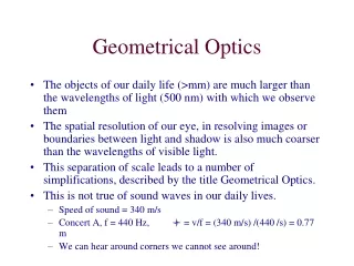
Differences between ACS and WFPC2 geometric distortion • Magnitude of distortion much greater (non-linear component in corners 50 pixels compared to 5) • The two ACS/WFC chips are rigidly mounted together. The four WFPC2 channels are separate optical systems and float relative to each other on many time scales. • ACS color-dependence is expected to be smaller than for WFPC2 as there are no refractive elements with power. • ACS has distortion correction in the pipeline using PyDrizzle/IDCTAB
Timeline of ACS Distortion Determinations • Ground calibrations based on Ronchi gratings (Cox et al.) • PyDrizzle and IDCTAB ready at time of ACS installation. • SMOV distortion program (Meurer, PI), April 2002. Dithered observations of 47Tuc through F475W. Distortion quartic coefficients for SBC/HRC/WFC. RMS much smaller than specification of 0.2 pixels. • Revised analysis to better determine skew terms, Cox, October 2002. Basis of IDCTAB in current pipeline. No filter dependence, but mechanisms in place to allow it. • Velocity aberration effects studied and incorporated into pipeline (Gilliland, Cox, Hack, 2003).
The Datasets used - 47 Tucanae calibration fields • Large numbers of datasets: • Both channels (HRC/WFC) • Most filters • Extended time coverage • Different orients • Optimal stellar densities
Anderson & King’s Analysis • Aim for highest possible accuracy to support relative astrometry - for most GO programs this is far higher than needed for (eg) image combination. • Data on 47 Tuc from initial distortion program (Meurer 9028), supplemental outsourced calibration program (King 9443) and L-flat program (Bohlin 9019). • PSF fitting methods developed (originally for WFPC2) which allow stellar positions to be determined to 0.005 pixels for bright stars in HRC (FLT, non-drizzled images used). • The data alone cannot provide scale information so the solution is relative to the scale of the central pixel (of one chip in WFC). • Relative scale is a free parameter between epochs and varies with velocity aberration and (smaller) breathing.
Results • Global distortion modeled well by 4th order polynomial (very close to Meurer solution) • Residuals (up to +/-0.1 pixel) are systematic, not well modeled by higher order polynomials, and stored as look-up-tables. For bright stars in the HRC the RMS is 0.005 pixels after the LUT is included: comparable to the measurement error. • Residuals are found to be a function of filter and to include small scale changes and offsets with filter. Jay has supplied “residual correction images” including the LUT information, relative to F475W. • Solutions appear to be stable over time. • Very detailed ISR on HRC available, WFC one in work.
F555W with F475W distortion polynomial. Same but with distortion correction table added.
Provisional Implementation of Anderson and King results for ACS/WFC/UDF • Just GOODS/UDF filters (f435w, f606w, f775w, f850lp). • Retained polynomial coefficients from current IDC solution. • Fitted planes to Jay Anderson’s residual correction images to extract shift/scale/skew components - Colin Cox has incorporated these into a provisional IDCTAB. • UPINWCS - Python task to take the IDCTAB information and update the image WCS to reflect scale changes, offsets and chip/chip offsets (and velocity aberration too). This puts all linear effects into the WCS. • Drizzle/wdrizzle software updated to allow residual correction images (after plane fit is subtracted) in addition to polynomials. • In use for UDF and appears to give excellent registration, eg, for SNe searching by subtraction. • Further detailed testing in progress (Jennifer Mack) with 47Tuc data - many filters, large dithers.
Residual Correction Images for F850LP - relative to F475W X-shift Y-shift WFC1 WFC2 Black = -0.4 pixels, Red = +0.4 pixels
F850LP - previous IDCTAB, no residual correction image47 Tuc, large dither, linear fit residuals, (sigma about 0.1 pixels)(Stellar position measurement accuracy about 0.05 pixels)
F850LP - latest, with residual correction image(sigma about 0.07 pixels)
Work remaining • Investigate small remaining residual effects • Improve star position measurements in tests (PSF fitting) • Use Jay Anderson’s final polynomials and residual correction images • Incorporate into PyDrizzle • Put updated software into ACS pipeline • Extend to all filters for both ACS/WFC and HRC • Document