Encoder factor
Encoder factor. Safety Parameters. Main Panel/Setup/Configurator. Main Panel/Setup/Adjuster/Safety Parameters. EFAC : 한 카운터가 나타내는 단위. FMASK : 체크된 기능을 사용한다 FDEF : 체크되면 , 내부적으로 설정된 동작을 한다 . 체크되지 않으면 , 프로그램적으로 동작시킨다 . SAFINI : 체크되면 , Fault 와 ^Fault 가 반전된다.

Encoder factor
E N D
Presentation Transcript
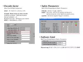
Encoder factor • Safety Parameters Main Panel/Setup/Configurator Main Panel/Setup/Adjuster/Safety Parameters EFAC : 한 카운터가 나타내는 단위 FMASK : 체크된 기능을 사용한다FDEF : 체크되면, 내부적으로 설정된 동작을 한다.체크되지 않으면, 프로그램적으로 동작시킨다.SAFINI :체크되면, Fault와 ^Fault가 반전된다. Example. Rotary motor & rotary encoderfeedback resolution : 2000 lines/rotationInternal multiplier : x4Required user unit : 360 degrees per rotationEFAC = 360/(2000x4) = 0.045 • Software Limit Main Panel/Setup/Adjuster/Safety Parameters Physical stop,에 닿기 전에, 미리 신호를 알려져 안정적으로STOP
Maximum Current/Torque Main Panel/Setup/Adjuster/Safety Parameters XRMS : Motor Nominal / DRIVER Peak) * 100XCURI : XCURI * 0.5XCURV : (Motor Peak / DRIVER Peak) * 100 • Mechanical Break Main Panel/Setup/Configurator XRMS : Motor Nominal / DRIVER Peak) * 100XCURI : XCURI * 0.5XCURV : (Motor Peak / DRIVER Peak) * 100 Main Panel/Setup/Configurator/MFLAGS
Axis Setup - General • Axis Setup - Drive Main Panel/Setup/Adjuster/Axis Setup/General Main Panel/Setup/Adjuster/Axis Setup/Drive Type – DC 1-input, 3Phase 2-input, 3Phase 1-input DC 1-input – Drive를 따로 갖춘 DC Motor 사용 시3Phase 2-input, Commutation by Controller– CM내부의 Drive를 사용하는 AC Servo/BLDC Motor3Pahse 1-input, Commutation by Amplifier– Drive를 따로 갖춘 AC Servo/BLDC Motor Control – Single loop Control, Dual loop Control Single loop – 하나의 motor에 하나의 encoder를 사용하여 위치 제어Dual loop–하나의 motor에 두개의 encoder를 사용하여 속도와 위치제어 Connection – Direct, Remote Direct – Controller가 Drive Port를 사용할 경우Remote– HSSI Module을 사용할 경우 • Axis Setup – Position Feedback • Axis Setup - Motor Main Panel/Setup/Adjuster/Axis Setup/Position Feedback Main Panel/Setup/Adjuster/Axis Setup/Motor Topology – Rotary, LinearType – Quadrature, Up-Down, Pulse-Direction, SIN-COS, Analog Topology – Rotary, LinearType – DC Brush, DC Brushless / AC Servo
Axis Setup Main Panel/Setup/Adjuster/Axis Setup
Stepper Drives(Pulse-Direction) Main Panel/Setup/Configurator/MFLAGS Control – Stepper-To-Encoder Loop, Stepper with Encoder Feedback Stepper-To-Encoder Loop – 입력 스텝이 곧 피드백 값이다Stepper with Encoder Feedback –외부에 Encoder를 장착한다. Main Panel/Setup/Configurator/MFLAGS
Open-Loop Verification 1. Motor Enable 한다. 2. Drive Output Range(%)를 10%로 맞춘다. 3. 조심스럽게 움직여 본다. 모터 폭주 주위 4. 엔코더 방향과 모터 방향이 같은지 본다. 5. 만약 다르다면 Feedback Configuration을 연다.
Velocity Loop Tuning • Velocity Loop Tuning 을 클릭 • Motion limited by를 Time Period 혹은 Between two Points중에 하나를 선택한다. • LPF Bandwidth를 650으로 셋 한다. • Integrator Gain 을 0으로 셋 한다. • Velocity Gain을 100으로 셋 한다. • Integrator Limit를 50%로 셋 한다. • Velocity를 최고의 10%만큼 변화시킨다. • Scope AutoSet을 클릭한다. • Motor를 Enable하고 Run한다. • Velocity Gain을 두배로 늘린다. • Integrator Gain을 오버슈터가 10-20%내로 들어오도 록 계속 증가시킨다. • Integrator Bandwidth는 50Hz를 넘지 안도록 한다. (Integrator Gain/20 = Integrator bandwidth)
Position Loop Tuning • Position Loop Tuning 을 클릭 • Select motion : Between two points, Positive direction only, Negative direction only • First point, Second point 설정 • Velocity, Acceleration, Deceleration을 원하는 동작의 최고값의 50%값으로 설정 • Scope Autoset 클릭 • Motor Enable & Run • Position Gain을 Position Error가 설정치를 벗어나지 않을 만큼 계속 증가시킨다.
Current Loop Tuning • Integrator Gain = 0 Set • Gain = 1000 Set • % of Peak Current = 10 • Pulse Length = 4 • Scope Autoset 클릭 • 약간의 Overshoot가 발생할 때까지 Gain증가 • Overshoot가 10~20%내로 계속 증가 • 위의 두 과정을 반복(만족할 때까지)