Project X Cryomodules
Project X Cryomodules. Tom Peterson and Yuriy Orlov with material from our SRF cavity and cryomodule design team 21 February 2011. 650 MHz Cryomodule Design, 21 Feb 2011. Page 1. Page 1. Project X Reference Design. Cryomodules for CW linac. 650 MHz Cryomodule Design, 21 Feb 2011.

Project X Cryomodules
E N D
Presentation Transcript
Project X Cryomodules Tom Peterson and Yuriy Orlov with material from our SRF cavity and cryomodule design team 21 February 2011 650 MHz Cryomodule Design, 21 Feb 2011 650 MHz Cryomodule Design, 21 Feb 2011 Page 1 Page 1
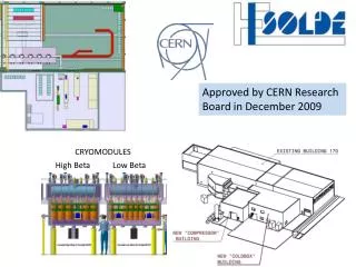
Project X Reference Design Cryomodules for CW linac 650 MHz Cryomodule Design, 21 Feb 2011 650 MHz Cryomodule Design, 21 Feb 2011 Page 2
SRF LinacTechnology Map Pulsed CW 650 MHz 0.16-3 GeV b=0.11 b=0.22 b=0.4 b=0.61 b=0.9 b=1.0 325 MHz 2.5-160 MeV 1.3 GHz 3-8 GeV InPAC 2011 – J. Kerby Page 3
Design team 650 MHz cryomodules Camille Ginsburg, Yuriy Orlov, and Prashant Khare are leading and organizing the effort with me Cavities, input couplers, magnets, magnet current leads, tuners, instrumentation, 325 MHz cryomodules, microphonics, etc. Many other people within Fermilab and within the Project X collaboration 650 MHz Cryomodule Design, 21 Feb 2011 650 MHz Cryomodule Design, 21 Feb 2011 Page 4
Approach CW cryomodules with as much as 25 W per cavity at 2 K and tight constraints on cavity frequency present some different problems from TESLA/ILC cryomodules Over 200 W at 2 K per cryomodule as opposed to about 12 W at 2 K per cryomodule Let’s look at the requirements, consider what other labs have already done, and select best features for our own design 650 MHz Cryomodule Design, 21 Feb 2011 650 MHz Cryomodule Design, 21 Feb 2011 Page 5
Our plan Analyses, modeling, and reviews of various concepts based on existing designs Following visits to HZB, DESY, and TTC meeting (Feb 21 - Mar 3), down-select a more specific design approach Goal is to have a specific 650 MHz cryomodule design proposal for discussion before the Project X Collaboration meeting (April 11) Also complete (draft) specifications and fundamental CM parameter lists in this timeframe 650 MHz Cryomodule Design, 21 Feb 2011 650 MHz Cryomodule Design, 21 Feb 2011 Page 6
General arrangements under consideration Segmentation level and cavity support structure String: BESSY/HZB (and Cornell ERL) liquid managed separately for each CM, 2-phase pipe closed at each end, but otherwise a string, TESLA style piping and supports Stand-alone: three options for configuration at the individual cryomodule level Completely close a TESLA style CM at each end Eliminate 300 mm pipe -- space frame support Eliminate 300 mm pipe -- support posts and frame (325 MHz concept from Tom Nicol) Helium vessel Closed, TESLA-style, 2-phase pipe connected to helium vessel Open, Jlab/SNS style, 2-phase flow through helium vessel 650 MHz Cryomodule Design, 21 Feb 2011 650 MHz Cryomodule Design, 21 Feb 2011 Page 7
Cryomodule style Very high heat flux (200 W per CM) and relatively short linac (not large quantity production nor several km long strings) ==> Need separated liquid management Prefer small heat exchangers, distributed with cryomodules Prefer stand-alone cryomodules, warm magnets and instrumentation between cryomodules like at SNS Stand-alone CM ==> “300 mm” pipe is unnecessary for helium flow Not need 300 mm pipe for helium flow ==> Empty 300 mm pipe as support ‘backbone” or Different support structure (space frame or posts) 650 MHz Cryomodule Design, 21 Feb 2011 650 MHz Cryomodule Design, 21 Feb 2011 Page 8
Helium vessel style Helium vessel style (open vs. closed) is independent of support style (hung from 300 mm pipe or not) High heat loads and tight pressure stability ==> Large liquid-vapor surface area for liquid-vapor equilibrium Acts as thermal/pressure buffer with heat and pressure changes Linac is short enough that total helium inventory not an issue ==> Open helium vessel is feasible For the stand-alone CW cryomodule, a closed TESLA-type helium vessel may be favored by Tuner design Input coupler design And allowed by reduced pressure sensitivity 650 MHz Cryomodule Design, 21 Feb 2011 650 MHz Cryomodule Design, 21 Feb 2011 Page 9
SNS vs TTF cryomodule TTF: vacuum vessel string. End boxes and bellows would become part of vacuum/pressure closure SNS (like CEBAF): self-contained vacuum vessel “stand-alone” style 650 MHz Cryomodule Design, 21 Feb 2011 650 MHz Cryomodule Design, 21 Feb 2011 Page 10
Cryomodule requirements -- major components Eight (8) dressed RF cavities Eight RF power input couplers One intermediate temperature thermal shield Cryogenic valves 2.0 K liquid level control valve Cool-down/warm-up valve 5 K thermal intercept flow control valve Pipe and cavity support structure Instrumentation -- RF, pressure, temperature, etc. Heat exchanger for 4.5 K to 2.2 K precooling of the liquid supply flow Bayonet connections for helium supply and return 650 MHz Cryomodule Design, 21 Feb 2011 650 MHz Cryomodule Design, 21 Feb 2011 Page 11
Cryomodule requirements -- major interfaces Bayonet connections for helium supply and return Vacuum vessel support structure Beam tube connections at the cryomodule ends RF waveguide to input couplers Instrumentation connectors on the vacuum shell Alignment fiducials on the vacuum shell with reference to cavity positions. 650 MHz Cryomodule Design, 21 Feb 2011 650 MHz Cryomodule Design, 21 Feb 2011 Page 12
Cryomodule requirements -- slot length 650 MHz cavities at 2 K 11.3 meters Warm magnets and instrumentation 650 MHz Cryomodule Design, 21 Feb 2011 650 MHz Cryomodule Design, 21 Feb 2011 Page 13
Cryomodule requirements -- thermal Cavities at nominally 2 K 1.8 K to 2.1 K, to be determined One radiative thermal shield at nominally 70 K 35 K to 80 K to be determined Thermal intercepts at nominally 5 K and 70 K 650 MHz Cryomodule Design, 21 Feb 2011 650 MHz Cryomodule Design, 21 Feb 2011 Page 14
Cryomodule requirements -- vessel and piping pressures 650 MHz Cryomodule Design, 21 Feb 2011 650 MHz Cryomodule Design, 21 Feb 2011 Page 15
Design considerations Cooling arrangement for integration into cryo system Pipe sizes for steady-state and emergency venting Pressure stability factors Liquid volume, vapor volume, liquid-vapor surface area as buffers for pressure change Evaporation or condensation rates with pressure change Updated heat load estimates Options for handling 4.5 K (or perhaps 5 K - 8 K) thermal intercept flow Alignment and support stability Thermal contraction and fixed points with closed ends Etc. 650 MHz Cryomodule Design, 21 Feb 2011 650 MHz Cryomodule Design, 21 Feb 2011 Page 16
Cryomodule Pipe Sizing Criteria Heat transport from cavity to 2-phase pipe 1 Watt/sq.cm. is a conservative rule for a vertical pipe (less heat flux with horizontal lengths) Two phase pipe size 5 meters/sec vapor “speed limit” over liquid Not smaller than nozzle from helium vessel Gas return pipe (also serves as the support pipe in TESLA-style CM) Pressure drop < 10% of total pressure in normal operation Support structure considerations Loss of vacuum venting P < cold MAWP at cavity Path includes nozzle from helium vessel, 2-phase pipe, may include gas return pipe, and any external vent lines 650 MHz Cryomodule Design, 21 Feb 2011 650 MHz Cryomodule Design, 21 Feb 2011 Page 17 17
650 MHz Cryomodule Design, 21 Feb 2011 650 MHz Cryomodule Design, 21 Feb 2011 Page 18
Concept -- TESLA style with open pipe as support Use an open 300 mm dia pipe as the support structure backbone Open to insulating vacuum Direct connection from 2-phase pipe to vapor return line via heat exchanger Direct connection from 2-phase pipe to vent line 2-phase pipe sized large for venting from one end Advantages 300 mm pipe open for handling with present tooling No end forces on 300 mm pipe or connections to it 650 MHz Cryomodule Design, 21 Feb 2011 650 MHz Cryomodule Design, 21 Feb 2011 Page 19
Stand-alone cryomodule schematic 650 MHz Cryomodule Design, 21 Feb 2011 650 MHz Cryomodule Design, 21 Feb 2011 Page 20
650 MHz Cryomodule (Tesla Style-Stand Alone) Vacuum vessel Cold mass supports (2+1) Power MC (8) Beam End Plate 650 MHz Cryomodule Design, 21 Feb 2011 650 MHz Cryomodule Design, 21 Feb 2011 Page 21 Page 21
650 MHz layout Sld. support Fix. support Sld. support 300mm pipe (backbone) 650 MHz cavity Gate valve End plate 650 MHz Cryomodule Design, 21 Feb 2011 650 MHz Cryomodule Design, 21 Feb 2011 Page 22 Page 22
X-Y section -48” vacuum vessel 300 mm pipe -80K shield, pipes: (Nom: 35mm-ID) -Warm up-cool down pipe (nom 25mm ID) -4K return pipe (nom 25mm ID) -650 MC -Thermal intercept to MC 80k & 4K -2-Phase pipe (161mm-ID) -80K Forward pipe -4K Forward pipe (?) -Thermal intercept 2-phase pipe to 300mm pipe (?) 650 MHz Cryomodule Design, 21 Feb 2011 650 MHz Cryomodule Design, 21 Feb 2011 Page 23 Page 23
650 MHz cryomodule. End plate not shown. Heat exchanger (Location on the middle of CM650??) 300mm pipe Access to bayonet connections Cryo-feed snout with cryogenic connections (Location on the middle of CM650??) Access to HX and U-turn connections Gate Valve 650 MHz Cryomodule Design, 21 Feb 2011 650 MHz Cryomodule Design, 21 Feb 2011 Page 24 Page 24
Cavity string & 300mm pipe upstream side Heat exchanger Vent line with check valve 2-phase pipe connection to HX Two He reservoirs with level sensor Cavity needle supports VAT needle supports (?) 650 MHz Cryomodule Design, 21 Feb 2011 650 MHz Cryomodule Design, 21 Feb 2011 Page 25 Page 25
Cavity string & 300mm pipe downstream side 2-phase pipe Thermal compensator Blank Flange support 650 MHz Cryomodule Design, 21 Feb 2011
Dressed cavity 650 MHz. (proposal) with MC cold-part Ti Helium vessel OD- 450.0 mm Ti 2-Phase pipe ID- 161.5 mm Ti 2-Phase chimney ID- 95.5 mm 650 MHz Cryomodule Design, 21 Feb 2011 650 MHz Cryomodule Design, 21 Feb 2011 Page 27 Page 27
Other concepts Single Spoke Resonator cryostat concept using support posts under the cavities and magnets We may adapt that design to a 650 MHz CM SNS/Jlab 12 GeV upgrade style “space frame” supports Well-developed design, works well BESSY/HZB CW cryomodule string rather than stand-alone cryomodules Eliminate external transfer line (?) Cornell’s ERL cryomodule has some interesting features to consider although somewhat different issues 650 MHz Cryomodule Design, 21 Feb 2011 650 MHz Cryomodule Design, 21 Feb 2011 Page 28
Conclusions Many very good ideas and much work have already gone into cryomodule design Systems are different with differing requirements Generally means adapting but not copying design concepts We greatly appreciate the exchange of ideas and information which have been and will continue to be an important part of our work 650 MHz Cryomodule Design, 21 Feb 2011 650 MHz Cryomodule Design, 21 Feb 2011 Page 29
Backup slides 650 MHz Cryomodule Design, 21 Feb 2011
Cryo Schematic -- flow through 300 mm pipe 650 MHz Cryomodule Design, 21 Feb 2011 650 MHz Cryomodule Design, 21 Feb 2011 Page 31 Page 31
Empty pipe for support only or no 300 mm pipe 650 MHz Cryomodule Design, 21 Feb 2011 650 MHz Cryomodule Design, 21 Feb 2011 Page 32 Page 32
SSR1 CM concept 650 MHz Cryomodule Design, 21 Feb 2011 650 MHz Cryomodule Design, 21 Feb 2011 Page 33
650 MHz Cryomodule layout (follwing SSR concept) Heat Exchanger pipe 2- phase He pipe (Ti) Vacuum vessel Cold mass 650 MHz Cavity 2 Support posts for each cavity: Z-fix & Z-free Cavity MC port -stabile 650 MHz Cryomodule Design, 21 Feb 2011 650 MHz Cryomodule Design, 21 Feb 2011 Page 34 Page 34
650 MHz Cryomodule (following SSR concept) Heat exchanger Vent line with check valve Control valves Bayonet connection Beam pipe: at the center of CM650 650 MHz Cryomodule Design, 21 Feb 2011 650 MHz Cryomodule Design, 21 Feb 2011 Page 35 Page 35
650 MHz Cryomodule section. (SSR-style concept) Heat exchanger Cryo feed snout Vacuum vessel pipe-48”OD XFEL style cavity (SNS style) 80K shielding Cold mass tray Tray supports 650 MHz Cryomodule Design, 21 Feb 2011 650 MHz Cryomodule Design, 21 Feb 2011 Page 36 Page 36
Jlab space frame 650 MHz Cryomodule Design, 21 Feb 2011 650 MHz Cryomodule Design, 21 Feb 2011 Page 37
Jlab space frame 650 MHz Cryomodule Design, 21 Feb 2011 650 MHz Cryomodule Design, 21 Feb 2011 Page 38
Jlab space frame 650 MHz Cryomodule Design, 21 Feb 2011 650 MHz Cryomodule Design, 21 Feb 2011 Page 39
Separate liquid management in each cryomodule but no external transfer line 650 MHz Cryomodule Design, 21 Feb 2011 650 MHz Cryomodule Design, 21 Feb 2011 Page 40
ERL injector cryomodule 650 MHz Cryomodule Design, 21 Feb 2011 650 MHz Cryomodule Design, 21 Feb 2011 Page 41
ERL cryomodule features Figure 1 from CRYOGENIC HEAT LOAD OF THE CORNELL ERL MAIN LINAC CRYOMODULE, by E. Chojnacki, E. Smith, R. Ehrlich, V. Veshcherevich and S. Chapman, Cornell University, Ithaca, NY, U.S.A. Published in Proceedings of SRF2009, Berlin, Germany 650 MHz Cryomodule Design, 21 Feb 2011 650 MHz Cryomodule Design, 21 Feb 2011 Page 42
ERL cryomodule features TESLA-style support structure -- dressed cavities hang from gas return pipe (GRP), but Titanium GRP No invar rod, no rollers 6 cavities per CM, 9.8 m total CM length HOM absorbers at 40 - 100 K between cavities GRP split with bellows at center, 4 support posts Helium vessels pinned to GRP Some flexibility in the input coupler De-magnetized carbon-steel shell for magnetic shielding (this is like TTF) 2-phase pipe closed at each CM end, JT valve on each CM (like BESSY design) String rolls into vacuum vessel on rails 650 MHz Cryomodule Design, 21 Feb 2011 650 MHz Cryomodule Design, 21 Feb 2011 Page 43
RRCAT contributions RRCAT (Indore) is collaborating with Fermilab on 650 MHz cryomodule designs Present focus is TESLA-style 650 MHz Cryomodule Design, 21 Feb 2011 650 MHz Cryomodule Design, 21 Feb 2011 Page 44
650 MHz Cryomodule Design, 21 Feb 2011 650 MHz Cryomodule Design, 21 Feb 2011 Page 45
Glimpses of 3-D Model (contd…) SCRF Cavity supported on HGR pipe • The model incorporates a modified Cavity support system. • 2K helium supply line includes a bellow in vertical configuration • Information required on • Magnet package • Tuner details • Power Coupler 650 MHz Cryomodule Design, 21 Feb 2011 650 MHz Cryomodule Design, 21 Feb 2011 Page 46
Glimpses of 3-D Model (contd…) Thermal Shield with dressed Cavity • 80K- Thermal shield • 5K-Thermal shield is partial (Upper Part only). • Thermal shield 80K shield . • Thermal shield 5K shield is partial. 650 MHz Cryomodule Design, 21 Feb 2011 650 MHz Cryomodule Design, 21 Feb 2011 Page 47