Project X Proton Driver
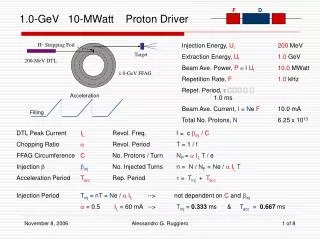
Project X Proton Driver. David Neuffer September 2011. 0utline. Introduction Proton Driver history Mission Project X Overview 3GeV cw Linac multiple output options 3 8 GeV pulsed linac extension to 4MW for Neutrino Factory/ Muon Collider 3 8 GeV variations FFAG

Project X Proton Driver
E N D
Presentation Transcript
Project XProton Driver David Neuffer September 2011
0utline • Introduction • Proton Driver history • Mission • Project X • Overview • 3GeV cwLinac • multiple output options • 38 GeV pulsed linac • extension to 4MW for Neutrino Factory/ Muon Collider • 38 GeV variations • FFAG • Discussion
Introduction • Since ~1995, Fermilab has identified an upgrade for the 8GeV Booster as its next major accelerator project • intensity, reliability, … • Various versions suggested • ~2GeV linac +16 GeV RCS ? • 8GeV 800MHz SRF linac ? • Foster • 1300 MHz (use ILC) • Project X • ICD-1 configuration • 8GeV pulsed SRF Linac • ~ILC SRF/ • Use 8GeV Recycler • Too expensive for DoE? • 1MW 8GeV beam ?
Project X mission and design (S. Nagaitsev et al.) • Mission goals • Provide 8 GeV beam to Main Injector for 2MW+ NUMI/NOvA/DuSELexpts. • Provide high-intensity medium-energy beams for fundamental process experiments • Provide a platform that can be extended to neutrino factory/muon collider applications (4MW ?) • ADS, nuclear physics, … • CD-2 • Centerpiece is 3GeV CW linac
Current Design Layout • 3 GeV CW linac • 650MHz rf • 1ma, 3MW • feeds experiments and • 38 GeVLinac • 1300MHz “ILC” cavities • 5% duty factor, 10Hz, 0.3MW • feeds Recycler/ Main Injector for DuSEL 3 GeV CW Linac 38 GeV pulsed Linac
Sergei Nagaitsev,Univer. of D0, May 5, 2011 Project X vs. other facilities
Project X 3-GeV beam is cw • Key innovation is cwlinac + rf splitter (like CEBAF) to serve many users • To form time structure add chopper at injector • (162.5 MHz RFQ with 5ma H-source ) • ~2×10⁸/bunch • arbitrarily kick out individual bunches at 2.5 MeV 1500MHz beam 500MHz in each exp
Chopping and splitting for 3-GeV experiments Ion source and RFQ operate at 4.2 mA -162.5MHz 75% of bunches are chopped at 2.5 MeV after RFQ Separation scheme 40.6 MHz deflector 0.75MW 10 MHz pulses Transverse rf splitter 1 MHz pulses 0.75MW 20 MHz pulses 1.5MW
Linac Systems overview RFQ Pulsed CW 650 MHz 0.16-3 GeV b=0.11 b=0.22 b=0.4 b=0.61 b=0.9 b=1.0 162.5 MHz or 325 0-2.5MeV 325 MHz 2.5-160 MeV 1.3 GHz 3-8 GeV
650 MHz cavities,cryomodules 650 MHz: β=0.9 650 MHz: β=0.61
38GeV for Main Injector • 38 GeV pulsed Linac • or RCS (FFAG?) • want 2+ MW at 60/120 GeV/ for DuSEL/ NOvA/… • 0.75/1.33s cycles • ~26ms-ma/pulse • too much for stripper? • Inject 6 ~4ms pulses into 8 GeV Recycler • 10Hz Linac 0.6s • transfer to Main Injector • ~320 kW maximum output power
162.5 /325 MHz must be chopped to fit 50MHz rf for Main Injector • ~3/5 bunches accepted • Injection requires “painting” to reduce foil hits and match into transverse acceptance
Upgrade to 4MW (for NF/MC) ? • Upgrade cwLinac to 5ma • 15 MW peak power • run at 10% duty cycle • Increase pulsed linac duty cycle to ~10% • 8GeV × 5ma × 10% = 4MW • Run at 15 Hz (6.7ms injection/cycle) • matches NF/MC scenarios • Chop at 50% for bunching • source/RFQ 10ma • Need Accumulator, • Compressor to bunch beam
Need 15/60 Hz bunches • Add Accumulator and Compressor Rings • ~8GeV rings • Accumulator captures and bunches beam • 2×10¹⁴ p, h=4 • Compressor: ¼ phase rotate to short bunch (combine onto target for MC) • Challenges • stripping injection: foil melts ? • Lattice design • large acceptance, δp/p • FMC lattice (Alexhin) • FFAG ?? From Linac: σ = 11m Accumulator: σ = 6.5m Compressor: σ = 0.5m
Current Status • Proposal Development and R&D • SRF development • 325 MHz • Cavity design , construction tests • 650 MHz • MOU with Jlab for 2 b=0.6 cavities • Order for six b = 0.9 cavities in industry • partnerships with India • 1300 MHz • ~ILC cavities and cryomodules • PXIE – Front End test stand • ~First 10 MeV of linac (~40m) • RFQ, Wide band Chopper • + initial 325 MHz rf • Workshops for Mission need • Construction status: • Still waiting for CD-0
3 8 GeV Alternative? • Use 3GeV: ~cw 1ma injector • avoid 5ma upgrade ? • 3 8 GeVFFAG • similar to IDS FFAG • Challenge to Workshop : Develop FFAG scenario for project X • Leo Jenner, J. Pasternak will discuss options • Would like scenario that can: • start with driver for Main Injector • upgradeable to 4MW (15/60Hz) • with bunch compression for NF/MC • be clearly more affordable than 38 GeVLinac + rings + …