Proton Driver Design
200 likes | 363 Vues
Proton Driver Design. Keith Gollwitzer Fermilab February 19, 2014. Proton Driver Outline. Overview History Accomplishments Current Concept Initial Baseline Selection Schedule Personnel and Effort Technology & Challenges. Proton Driver at August 2012 MAP Review. Overview

Proton Driver Design
E N D
Presentation Transcript
Proton Driver Design Keith Gollwitzer Fermilab February 19, 2014
Proton Driver Outline Keith Gollwitzer | DOE Review of MAP (FNAL, February 19-20, 2014) • Overview • History • Accomplishments • Current Concept • Initial Baseline Selection Schedule • Personnel and Effort • Technology & Challenges
Proton Driver at August 2012 MAP Review Keith Gollwitzer | DOE Review of MAP (FNAL, February 19-20, 2014) • Overview • Assumed Project X existed • Outlined how to increase Project X beam to 4 MW of 8 GeV H- ions • Accumulation Ring converts ions to protons as well as formats beam into a few intense bunches • Compressor Ring bunch rotates beam to the desired short bunch(s) • Delivery beam line(s)
Since Last August 2012 MAP Review Keith Gollwitzer | DOE Review of MAP (FNAL, February 19-20, 2014) • Project X was split into stages • MASS looked at facilities starting with stage 2 of Project X • Proton Driver at 3 GeV • Proton Improvement Plan (PIP) II has become the start of a new facility for the Proton Driver • MASS assumes that there is a follow-on to PIP II resulting in the equivalent of stage 2 • MASS proposes Dual Use Linac • Proton Driver delivers 6.75 GeV proton beam
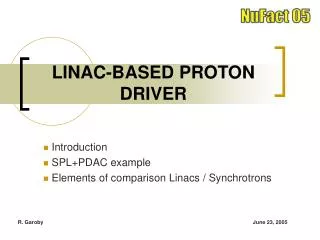
Dual Use Linac 1.25-5 GeV 0.2-1.25 GeV 1-3 GeV 3-6.75 GeV Keith Gollwitzer | DOE Review of MAP (FNAL, February 19-20, 2014) • MAP linac for muon acceleration can be used for H- acceleration • muon beam 1.25 - 5 GeV • H- beam 3 - 6.75 GeV • FNAL SRF expertise is 325 MHz, 650 MHz and 1300MHz • MAP has moved to adopt these frequencies
Key Proton Driver Accomplishments Since the August 2012 MAP Review Keith Gollwitzer | DOE Review of MAP (FNAL, February 19-20, 2014)
Present Day Assumptions Keith Gollwitzer | DOE Review of MAP (FNAL, February 19-20, 2014) • PIP II: Ion source (5mA) & RFQ (162.5 MHz) provides 1.92 x 10⁸ particles per linac bunch. • Follow on to PIP II: an additional non-MAP linacsupporting high power beam to 3 GeV. • Similar to Stage 2 of Project X • 1 MW scenario: Dual Use Linacaccelerating ions at 15 Hz to 6.75 GeV • 4 ms pulses where 50% beam is chopped in front end so that linac bunches are synched with Accumulator Ring RF
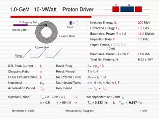
Revisit of Rings’ Designs Accumulator Compressor Keith Gollwitzer | DOE Review of MAP (FNAL, February 19-20, 2014) Previous work had been for 8 GeV
Revisit of Rings’ Designs Keith Gollwitzer | DOE Review of MAP (FNAL, February 19-20, 2014) • Previous work has been for 4 MW at 8 GeV • Start by revisiting rings for 1 MW at 6.75 GeV • Follow with larger beam power studies
Stripping System Keith Gollwitzer | DOE Review of MAP (FNAL, February 19-20, 2014) • Conversion of MW (or more) ion beam to protons for accumulation will be studied. • Stripping at 6.75 (or 8) GeV • Leveraging • SNS experience: 1 MW at 1 GeV • Continue Project X work: 300kW at 8 GeV • Same FNAL personnel involved • Ideas • Foil (stationary, multiple, rotating) • Laser stripping
Delivery Beam Line(s) & Focusing System Keith Gollwitzer | DOE Review of MAP (FNAL, February 19-20, 2014) • Based upon IDS-NF design. • Focusing system will be interfaced with Target system. • Bunch instabilities may require extraction of several bunches from the Compressor Ring to be sent through different beam lines to arrive simultaneously at the target. • Focusing system could require a non-standard magnetic element(s) that focuses multiple beams that have little separation
Initial Baseline Selection Schedule Keith Gollwitzer | DOE Review of MAP (FNAL, February 19-20, 2014)
Personnel & Effort Required Keith Gollwitzer | DOE Review of MAP (FNAL, February 19-20, 2014) A magnet expert is available for consulting Effort to reach IBS will be 1 FTE x 20 months
Conventional Technology Keith Gollwitzer | DOE Review of MAP (FNAL, February 19-20, 2014) • Ring and beam line magnets • Dipoles • Quads • Sextupoles • Kickers • RF Systems • Collimators
Novel Technologies Keith Gollwitzer | DOE Review of MAP (FNAL, February 19-20, 2014) • Stripping System • Greater than 1 GeV ion beam energy • Greater than 1 MW beam power • Target Focus System • Focus element(s) within greater than 1 T solenoid magnetic field • Multiple beams with small separation being focused
Stripping System Challenges Will extend on-going work for linac beam conversion to protons and injection into the Main Injector Keith Gollwitzer | DOE Review of MAP (FNAL, February 19-20, 2014) • Static Foil or Rotating Foil • What beam power can be endured? • Multiple beam passes. Scattering. • Laser • Viability for MW beam • Unconverted Beam • Capture of non-protons (dump) • Limit activation of tunnel and components
Focus System Challenges Keith Gollwitzer | DOE Review of MAP (FNAL, February 19-20, 2014) • Target Solenoid Field • A “fringe” field > 1 T exists 5 m upstream of target • Magnetic shielding or canceling magnetic field • Off-axis proton beam path is helical • Multiple beams with small crossing angles at target • Previous work showed that the separation of 4 beams 5 m upstream of target to be ~15 cm.
Proton Driver Conclusion Keith Gollwitzer | DOE Review of MAP (FNAL, February 19-20, 2014) • Design work • Revisit of rings designs almost complete • Delivery beam line to be based upon IDS-NF • Technology • Most components are conventional • Stripping system will be leveraged from SNS experience and work done for linac beam injection into the Main Injector • Final Focusing element(s) may require design of a non-conventional magnet
Extras Keith Gollwitzer | DOE Review of MAP (FNAL, February 19-20, 2014)
Possible Layout Final Cool 6DCool 1 GeV Proton Linac Initial Cool Accumulator & CompressorRings Front End 1-3 GeV Proton Linac To SURF Target NuMAX: ns to SURF 1 GeV Muon Linac (325MHz) RLA to 63 GeV 3-6.75 GeV Proton &1.25-5 GeV MuonDual Use Linac 300m Higgs Factory Muon Collider Keith Gollwitzer | DOE Review of MAP (FNAL, February 19-20, 2014)