Download
1 / 30
300 likes | 520 Vues
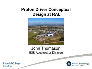
Proton Driver Conceptual Design at RAL. John Thomason. ISIS Accelerator Division. Reference IDS Neutrino Factory Design. High Power Proton Driver. Supply protons to target to produce pions. Basic specifications: 4 MW proton beam power. Proton kinetic energy 5 – 15 GeV.

E N D
Proton Driver Conceptual Design at RAL John Thomason ISIS Accelerator Division
High Power Proton Driver • Supply protons to target to produce pions • Basic specifications: • 4 MW proton beam power • Proton kinetic energy 5 – 15 GeV • RMS bunch length 1 – 3 ns • 50 Hz repetition rate • Three bunches, extracted > 80 µs apart
Current Options for NF Proton Driver • Linac based (SPL) proton driver at CERN – the most advanced • Synchrotron(s)/FFAG based proton driver (green field solution) – under study at RAL • Project X based solution at Fermilab • Solution based on synergy between neutron spallation source(ISIS MW upgrade) • and NF – idea shared by many people • Other solutions (multiple FFAGs, NS-FFAGs, etc.) – in the state of ideas
Proton Driver for a Neutrino Factory Chris Prior, Grahame Rees, Shinji Machida ( ) • Lower injection energies provide smaller • bucket area in the ring and the • small longitudinal emittance • needed for final ns bunch • compression. Studies • show that 180 MeV is a • realistic energy for NF • Separate main ring with optics chosen • for ns bunch compression. Could • be FFAG (cheaper but • insufficiently developed) or • a synchrotron (reliable, • tried and tested) • Special achromat for • collimation (longitudinal • and transverse) and • momentum ramping for • injection • Compressed • bunches need to be held and sent to • target at intervals of ~100 μs. Possible in FFAG and also synchrotron with flat top • Separate booster ring • designed for low loss phase • space painting for beam injection • and accumulation. Synchrotron moving • buckets give flexibility to capture all of the • injected beam
10 GeV ns-FFAG Proton Driver • High intensity ~1014 protons • Achieved with phase space painting • in RCS booster • 50 Hz rep rate • Booster circumference 400 m • Bunch area (h = 3) 1.1 eVs • ns bunch compression • Achieved with FFAG accelerator • 1.3 MV per turn for 3.0 ns RMS, • improved by higher harmonic • component to 1.9 ns • FFAG circumference ~800 m • Delayed extraction of bunches to meet • requirements of muon accelerators and • decay rings • May be easier with FFAG than • synchrotrons
10 GeV ns-FFAG Proton Driver • ns-FFAG chosen for: • Lower RF accelerating fields • Ability to hold compressed bunches • at top energy • Metallic vacuum chambers (c.f. ceramic • with RF shields for RCS) • Uses h = 24, 1.3 MV per turn for 3.0 ns • bunch compression Pumplet (Grahame Rees) • Non-linear, combined function magnets • with exit-entry faces parallel • Tunes per cell νx = 4 , νy = 3 ; • 66 cells,Qx = 20 4 , Qy = 15 3 • Zero chromaticity at each reference • energy orbit • Large dynamic aperture 13 13 13 13
10 GeV RCS Proton Driver • High intensity ~1014 protons • Achieved with phase space painting • in RCS booster • 50 Hz rep rate • Booster circumference 400 m • Bunch area (h = 3) 1.1 eVs • ns bunch compression • Achieved with RCS accelerator • (h = 24) • 1.3 MV per turn for 3 ns RMS • compression • RCS circumference same as for • FFAG (~800 m) • • Finemet, rather than ferrite, could be • used for rf cavities RCS Main synchrotron 3 GeV RCS Booster 0.2 GeV H− linac
10 GeV RCS Proton Driver • 10 GeV RCS: • Circumference ~800 m; γt ~20 • Doublet cells to provide long • dispersion-free straights • Uses h = 24, 1.3 MV per turn for 3.0 ns • bunch compression • Voltage mid-cycle reduced through use • of dual harmonic magnetic guide field, • B(t) = B0 – B1cos2πft + B2cos4πft
3 GeV Booster RCS • 50 Hz RCS preferred to FFAG; • more efficient H− injection • 7 triplet cells in four superperiods, • long (10.6 m) free straight sections • Separate superperiods for collimation, • RF and extraction • Injection in 8º low field dipole (~0.055 T) • with Dx/√βx= 1.9 m½ for horizontal phase • space painting, using RF steering and • momentum ramping; vertical painting • with conventional bump magnets – avoids • need for injection chicane • Beam power in booster is 1.2 MW – higher than • for any existing RCS • Over 100 m provided for RF system • Booster uses h = 3, 0.85 MV per turn for 1.1 eVs bunches • Foil heating from stripping and subsequent proton • traversals is a concern
Achromat and Collimation Beam Line • Beam prepared for injection in achromatic arc between Linac and booster ring • Combined function magnets, 8 with +45º bends, 4 with -45º bends • Length 41.6 m normalised dispersion D/√β=5.1 m½ • Horizontal and vertical beam loss collimators, cavities for momentum spread • reduction and correction • Stripping foils for momentum collimation
0.24 MW ISIS • Assumes an optimised 2RF • system giving 300 µA in the • synchrotron • 4/5 pulse pairs to TS-1 • (192 kW) and 1/5 pulse pairs • to TS-2 (48 kW) • Must keep beam to TS-2 for • the foreseeable future
ISIS MW Upgrade Scenarios Further developments of the ISIS accelerator and target stations are possible with each stage giving of order a factor 2 enhancement of the neutron source characteristics 0) Linac and TS1 refurbishment 1) Linac upgrade leading to ~0.5 MW operations on TS1 2) ~3.3 GeV booster synchrotron: MW Target 3) 800 MeV direct injections to booster synchrotron: 2 – 5 MW Target 4) 800 MeV direct injections to booster synchrotron + long pulse mode option overlap with NF proton driver
ISIS MW Upgrade Scenarios 1) Replace ISIS linac with a new ~180 MeV linac (~0.5MW) 2) Based on a ~3.3 GeV RCS fed by bucket-to-bucket transfer from ISIS 800 MeV synchrotron (1MW, perhaps more) 3) RCS design also accommodates multi-turn charge exchange injection to facilitate a further upgrade path where the RCS is fed directly from an 800 MeV linac (2 – 5 MW)
2) Lattice and high intensity studies for a ~3.3 GeV booster synchrotron and associated beam lines: ISIS, ASTeC and Imperial College staff. • - This upgrade would make ISIS competitive (in terms of raw beam power) with the facilities now being commissioned at SNS in the USA and JPARC in Japan. • - A full physics design, integrated with the 800 MeV Linac design below, would follow on from that for the upgraded ~180 MeV Linac, and is scheduled to be carried out in 2011/2012, ready for engineering and costing input and the design of a new target station. • Much of the necessary development and benchmarking of simulation codes, upgrade of computing power and study of key high intensity phenomena on ISIS will overlap with that required for the ~180 MeV Linac upgrade. • All MW upgrade designs will incorporate TS2 running at its full capacity. • If possible will remain compatible with UKNF proton driver plans.
Grahame Rees ( ) Chris Warsop, Dean Adams, Ben Pine, Bryan Jones, Rob Williamson ( ) Possible ~3.3 GeV RCS Rings
3) 800 MeV high intensity Linac design – ASTeC Intense Beams Group and FETS Collaboration staff. - This addition to the facility would allow direct injection into the ~3.3 GeV booster synchrotron, giving 2 – 5 MW of beam power. - Beam dynamics studies for this upgrade can be carried out in parallel with the upgraded ~180 MeV Linac and ~3.3 GeV booster synchrotron, giving a full, integrated physics design by 2012. - Engineering and costing are only sensible at the point when funding for a ~3.3 GeV booster synchrotron has been approved, unless these options are to be considered together as a stand alone facility, separate from the present ISIS. - This high intensity Linac design could also be the basis for an additional long pulse mode option in the future.
800 MeV, Hˉ Linac Design Parameters Grahame Rees, Ciprian Plostinar ( )
Design Options • All options have the same 324 MHz, 74.8 MeV stage 1: RFQ MEBT DTL IEBT 74.8 MeV Options F (MHz) Stage 2 Stage 3 Stage 4 1 648 ScL 1 ScL 2 ScL 3 2 648 CCL ScL 2 ScL 3 3 (324) 972 (ScL a) ScL b ScL c ~200 MeV 800 MeV
Beam Sizes in 800 MeV Linac & Beam Line ScL1 ScL2 ScL3 H V Δφ Debunching line
Common Proton Driver for theNeutron Source and the Neutrino Factory • Based on MW ISIS upgrade with • 800MeV Linac and 3.2 (~3.3) GeV RCS • Assumes a sharing of the beam power • at 3.2 GeV between the two facilities • Requires additional RCS machine • in order to meet the power and energy • needs of the Neutrino Factory • Both facilities can have the same • ion source, RFQ, chopper, linac, • H− injection, accumulation and • acceleration to 3.2 GeV Additional RCS ISIS MW upgrade
Summary of Assumptions for the Common Proton Driver • 3 bunches will be transfered from the booster RCS at 3.2 GeV and 2 MW • Acceleration by a factor of 2 is needed to get the necessary 4 MW (to 6.4 GeV) • Some beam parameters at injection: • - longitudinal emittance 1.8 eVs • - total bunch length 110 ns • - intensity 2.6x10¹³ protons/bunch • - 3 bunches • Options for the bunch compression to 1 – 3 ns RMS bunch length: • - adiabatic compression in the RCS • - ‘fast phase rotation’ in the RCS • - ‘fast phase rotation’ in a dedicated compressor ring
Preliminary design of the second RCS Jaroslaw Pasternak ( , ) Parameters of 6.4 (10.3) GeV RCS • Lattice may allow for flexibility in gammatransition choice (even with beam) • Ring is overdesigned in order to allow for10.3 GeV • Optimised solution for 6.4 GeV is in preparation!
Alternative Proton Driver Layout NF target 4 MW 3 bunches 800 MeV H- linac RCS 3.2 GeV 50 Hz RCS 6.4 GeV 50 Hz Compressor ring Neutron target, 2.6 MW • Fast phase rotation in the dedicated compressor ring • (most economic from the RF point of view, but another ring is needed) • Bunches will be extracted one by one from the RCS • Compressor ring works above transition, but the rotation is very fast • The bunches in the RCS will wait uncompressed for 200 µs • We do not have a design for the compressor ring at the moment, • but CERN design can be adopted
Summary and Future Plans • Parameters needed for the Neutrino Factory Proton Driver are still evolving • (pulse length, energy?), but this will not change too much in the design • Several solutions are advancing well to be able to meet the goal • A common proton driver compatible with the ISIS MW upgrade is a very • attractive solution to create a cost effective multi-user facility, but careful • attention must be given to potential conflicts of interest between the neutron • and neutrino communities. • More work is needed on the bunch compression scenarios.
Necessary R&D To realise ISIS MW upgrades, UKNF and generic high power proton driver development, common hardware R&D will be necessary in key areas: • High power front end (FETS) • RF Systems • Stripping Foils • Diagnostics • Targets • Kickers • etc. • In the neutron factory context SNS and J-PARC are currently dealing with • many of these issues during facility commissioning and we have a watching • brief for all of these • Active programmes in some specific areas
NF on RAL/HSIC Site Norsaq x