LINAC-BASED PROTON DRIVER
This document provides an overview of Linac-based proton drivers and their comparison to synchrotron accelerators for high-energy physics applications. It highlights the advantages of Linacs in low-energy acceleration and the necessary integration of synchrotrons for higher energy accumulation. The paper discusses the SPL and PDAC projects at CERN, aiming to enhance accelerator performance and address future experimental requirements, including new facets of research in neutrinos and radioactive ion beams. Cost and energy comparisons are included to inform design decisions.

LINAC-BASED PROTON DRIVER
E N D
Presentation Transcript
LINAC-BASED PROTON DRIVER Introduction SPL+PDAC example Elements of comparison Linacs / Synchrotrons
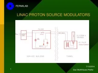
Introduction All proton driver begin with a linear accelerator. In a Linac-based driver, all acceleration is done in the Linac. However a fixed energy synchrotron is still needed for accumulation and bunch compression. At low energy, it makes sense to only accelerate in a linac. Progress in sc resonators are reducing cost. However, at high energy (>5-8 GeV ?), a linac will anyhow be too costly. • What is the limit energy for selecting acceleration in the synchrotron ? • Other arguments ? 2
SPL & PDAC [1/3] SPL (CDR2) characteristics 3
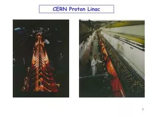
SPL & PDAC [2/3] SPL main goals: • increase the performance of the CERN high energy accelerators (PS, SPS & LHC) • address the needs of future experiments with neutrinos and radio-active ion beams The present R&D programme concentrates on low-energy (Linac4) items, wherever possible in collaboration with other laboratories. 4
SPL & PDAC [3/3] SPL (CDR2) + PDAC characteristics [Extrapolation from PDAC based on the SPL CDR-1] 5
ANNEX 9
Cost comparison Cost Energy 10
SPL - CDR2 baseline • RF • 704 MHz bulk Niobium cavities • 3 families of cavities : beta =0.5,0.85,1.0 • gradients : 15, 18, 30 MV/m • 5, 6 and 7 cells per cavity • Cold (2K) quadrupoles in the cryomodules, independently aligned from the cavities (to minimize cold/warm transitions and maximize real estate gradient). • Cryomodules of maximum length (between 10 and 15 m), containing n cavities and (n+1) quadrupoles. Diagnostics, steering etc. between cryomodules. • Length of the cavities limited by fabrication and handling considerations. Proposed number of cells per cavity is therefore 5, 6 and 7 for the three sections. • 2 MW max power /coupler • Standardisation of the design after 2 GeV 11
HIP WG: long term alternatives <- * with brightness x2 ** need new injector(s) 12