Download
1 / 21
240 likes | 407 Vues
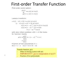
Homodyne detection: understanding the laser noise amplitude transfer function. J érô me Degallaix Ilias meeting – June 2007. Going DC. Stefan’s talk this morning. Laser. PRM. SRM. Carrier local oscillator. Measure the laser intensity noise transfer function.

E N D
Homodyne detection:understanding the laser noise amplitude transfer function Jérôme Degallaix Ilias meeting – June 2007
Going DC Stefan’s talk this morning Laser PRM SRM Carrier local oscillator
Measure the laser intensity noise transfer function • Switch off laser power stabilisation loop • Inject white noise into the laser pump • Record dark port spectrum
Input ? Reflected PRC Laser After laser After MC Reflected BS output
Optical fields FSR = 125 kHz Laser
Optical fields FSR = 125 kHz fMI = 14.9 MHz Laser
Optical fields FSR = 125 kHz fMI = 14.9 MHz fSR = 9.01 MHz Laser
Carrier TF Simple Michelson • Flat response due: • Arm asymetries • Dark fringe offset
Carrier TF With SRM Peak due to SRM
Carrier TF Including the higher order optical modes • Increase the amplitude of the TF • Flat the response at high frequency
TF with SR sidebands Resonance peak of the sidebands!
TF with SR sidebands Including the higher order optical modes Shape of the sidebands resonance different!
TF with MI sidebands Including the higher order optical modes
Changing the PRC FSR A little test to confirm what we understand...
Changing the SRC FSR Another test...
Does it match the experiment ? • Adjust the overall gain of the simulated TF • Thanks to Andreas for the tuning of the parameters
To sum up... Due to the signal recycling mirror Due to SR sidebands and higher order optical modes • Overal magnitude depends of: • arm detuning • magnitude of higher order optical modes Due to second order optical modes Due to MI sidebands

![1. X resolution[95] AROC Curve BModulation Transfer Function CH D Curve DContrast-Detail Curve](https://cdn4.slideserve.com/1390808/slide1-dt.jpg)