Download

1 / 82
830 likes | 1.13k Vues
The Challenger Disaster. Prof Michael D. Smith School of Physical Sciences (pictures and some text reproduced from NASA sources). Lecture outline. Build-up to the 1986 mission. Analysis of the Space Shuttle break-up. Presidential Commission Report. Conclusions.

E N D
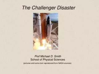
The Challenger Disaster Prof Michael D. Smith School of Physical Sciences (pictures and some text reproduced from NASA sources)
Lecture outline • Build-up to the 1986 mission. • Analysis of the Space Shuttle break-up. • Presidential Commission Report. • Conclusions. • Further details.
Columbia history Milestones – OV102 July 26, 1972 Contract Award Nov. 21, 1975 Start structural assembly of crew module June 14, 1976 Start structural assembly of aft-fuselage March 16, 1977 Wings arrive at Palmdale from Grumman Sept. 30, 1977 Start of Final Assembly Feb. 10, 1978 Completed final assembly Feb. 14, 1978 Rollout from Palmdale April 12 1981 Launch Jan 16, 2003 28th and Last Flight
Challenger history. Construction Milestones - OV-099 (Space shuttle Challenger) Jan. 1, 1979 Contract Award Jan. 28, 1979 Start structural assembly of crew module June 14, 1976 Start structural assembly of aft-fuselage March 16, 1977 Wings arrive at Palmdale from Grumman Nov. 3, 1980 Start of Final Assembly Oct. 21, 1981 Completed final assembly June 30, 1982 Rollout from Palmdale July 1, 1982 Overland transport from Palmdale to Edwards July 5, 1982 Delivery to Kennedy Space Center Dec. 19, 1982 Flight Readiness Firing April 4, 1983 First Flight (STS-6) January 28, 1986 10th and Last Flight
Challenger firsts. • Challenger launched on her maiden voyage, STS-6, on April 4, 1983. • That mission saw the first spacewalk of the Space Shuttle program, • as well as the deployment of the first satellite in the • Tracking and Data Relay System constellation. • The orbiter launched the first American woman, Sally Ride, • into space on mission STS-7 • and was the first to carry two U.S. female astronauts • on mission STS 41-G.
Challenger history. Challenger against a backdrop of blue water and white clouds taken from a camera aboard the Shuttle Pallet Satellite during mission STS-7.
Background to the mission. 1986 National Aereonautics and Space Administration • This would be the busiest year ever for NASA. • Halley's comet would be observed. • The Hubble telescope lofted. • 25th shuttle flight. • The first average American in space.
Shuttle Mission STS-51L: problems Shuttle Mission was plagued by problems from onset. weather conditions technical problems
Shuttle Mission STS-51L: delays Challenger was originally scheduled for July, 1985, but by the time the crew was assigned in January, 1985, launch had been postponed to late November to accommodate changes in payloads. The launch was subsequently delayed further and finally rescheduled for late January, 1986.
Shuttle Mission STS-51L Launch delays Liftoff was initially scheduled January 22, 1986. It slipped to Jan 23 then Jan. 24, reset for Jan. 25, rescheduled for Jan. 27, but delayed another 24 hours. The Challenger finally lifted off at 11:38:00 a.m. EST, 28th Jan.
Shuttle Mission STS-51L Launch delays The first delay of the Challenger mission was due to a weather front expected to move into the area, bringing rain and cold temperatures. Vice President expected to be present for the launch and NASA officials postponed the launch early. The Vice President was a key spokesperson the space program, NASA coveted his good will.
Shuttle Mission STS-51L Launch delays The second launch delay was caused by a defective microswitch in the hatch locking mechanism and problems in removing the hatch handle. Once these problems had been sorted out, winds had become too high. The weather front had started moving again, and appeared to be bringing record-setting low temperatures to the Florida area.
Mission details Challenger was scheduled to carry some cargo • Tracking Data Relay Satellite-2 (TDRS-2) • Shuttle-Pointed Tool for Astronomy (SPARTAN-203) Halley's Comet Experiment Deployable free-flying module designed to observe Halleys comet using two ultraviolet spectrometers and two cameras.
The Crew Back row from left to right: Mission Specialist, Ellison S. Onizuka, Teacher in Space Participant Sharon Christa McAuliffe, Payload Specialist, Greg Jarvis and Mission Specialist, Judy Resnik. In the front row from left to right: Pilot Mike Smith, Commander, Dick Scobee and Mission Specialist, Ron McNair.
Mission Highlights (Planned)On Flight Day 1: • Arrive in orbit. • Check the readiness of the TDRS-B satellite. • Deploy the satellite • and its Inertial Upper Stage (IUS) booster. On Flight Day 2: • The Comet Halley Active Monitoring Program • CHAMP) experiment scheduled to begin. • ”Teacher in space" (TISP) video taping. • Firing of the orbital maneuvering engines (OMS) • at 152-mile altitude from which the • Spartan would be deployed.
Mission Highlights (Planned)On Flight Day 3: • Pre-deployment preparations on the Spartan. • Deployment using remote manipulator system • (RMS) robot arm. • Separate from Spartan by 90 miles. On Flight Day 4: • Continue fluid dynamics experiments (started on day 2 and day 3). • Challenger begin to close in on Spartan • Live telecasts by Christa McAuliffe.
Mission Highlights (Planned)On Flight Day 5 Rendezvous with Spartan Use the robot arm to capture the satellite. . On Flight Day 6 Re-entry preparations, including flight control checks, test firing of maneuvering jets Crew news conferences also scheduled On Flight Day 7 Prepare for deorbit and re-entry Scheduled to land at the Kennedy Space Center 144 hours and 34 minutes after launch.
External Tank Basic shuttle design Right Solid Rocket Booster Left Solid Rocket Booster Orbiter
Length 37.2m • Height 17.25m • Mass 68.5tonnes • Payload:32,000kg • Crew: 7 max 1. Orbiter • The primary component: • A reusable, winged craft containing the crew and payload • that actually travels into space and returns to land on • a runway.
2. External Tank • The External Tank carries liquid oxygen and liquid • hydrogen in two separate compartments. This is the fuel • that is fed to the three orbital engines. The ET is jettisoned at an altitude of 111,400m (365,000ft), and burns-up over the Indian Ocean.
External Fuel Tank • Mass: 30 tonnes, empty. • Lift off mass 762 tonnes. • The skeleton of the shuttle vehicle assembly. • The tank holds: 550,000L LOX 1,500,000L LH2 • Only part of the shuttle system to be thrown away.
3. Solid rocket boosters • Without the SRBs, the shuttle cannot produce • enough thrust to overcome the earth's gravitational pull. • An SRB is attached to each side of the external fuel tank. • Each booster is 149 feet long (45m) and • 12 feet (3.6m) in diameter. • Before ignition, each booster weighs 2 million pounds • (900 tonnes, 150 elephants). • 80% of the total vehicle mass, 83% of total thrust
Solid rocket booster • SRBs, in general, produce much more thrust per weight • than their liquid fuel counterparts. • The drawback is that, once the solid rocket fuel has • been ignited, it cannot be turned off or even controlled. • Morton Thiokol was awarded the contract to design and • build the SRBs in 1974. • Thiokol's design is a scaled-up version of a Titan missile, • which had been used successfully for years. • NASA accepted the design in 1976.
Solid rocket booster • After the SRBs have lifted the Shuttle to an altitude • of about 150,000 ft (45,760 m), the SRBs are jettisoned • using small explosive charges. • The SRBs then deploy parachutes • and fall into the ocean. • they are recovered by tugs.
Pressurised Joint deflection on Solid Rocket Booster Interior Exterior Exterior Interior O-rings Pressurised joint (exaggerated) Unpressurised joint
Solid rocket booster Each SRB joint is sealed by two O-rings: the bottom ring known as the primary O-ring, and the top known as the secondary O-ring. The purpose of the O-rings is to prevent hot combustion gasses from escaping from the inside of the motor. Putty: To provide a barrier between the rubber O-rings and the combustion gasses, a heat-resistant putty is applied to the inner section of the joint.
Solid rocket booster O-Rings The Titan booster had only one O-ring. The second ring was added as a measure of safety. Except for the increased scale of the rocket's diameter, this was the only major difference between the shuttle booster and the Titan booster.
Temperature on day of the launch The air temperature had dropped to -8°C (18°F) the night before and 36°F (2°C) on the morning of the launch. No previous flight had been attempted below 11°C (51°F ), and the manufacturer, Morton Thiokol, had insufficient data on how the boosters would perform at lower temperatures. Although Thiokol engineers were concerned about launching under these conditions and recommended a delay, many felt that the boosters should be able to operate safely even at that low of a temperature.
Wind blowing over the ET and impinging on the aft field joint of the right SRB Wind Super-cooled air descending Aft Field Joint O-ring Lower Attachment Strut
Cold conditions pre-launch It is common procedure for ground personnel to use infrared cameras to measure the thickness of the ice that forms on the ET prior to launch. By chance, the Ice Team happened to point a camera at the aft field joint of the right SRB and recorded a temperature of only 8°F (-13°C), much colder than the air temperature and far below the design tolerances of the O-rings. Had this wind been blowing in almost any other direction and not impinged on the aft field joint, it is likely that the O-rings would have been considerably warmer and the disaster may not have occurred.
Cold conditions pre-launch An additional factor was that the information collected by the Ice Team was never passed on to decision makers, primarily because it was not the Ice Team's responsibility to report anything other than the ice thickness on the ET. Had the aft field joint temperature been provided to engineers at NASA and Morton Thiokol, the launch almost surely would've been aborted and the loss of Challenger avoided.
Countdown and launch The Challenger was counted-down and lifted-off at 11:38:00 a.m. EST, 28th Jan.
O-ring blow-by from the right SRB 0.678 sec
O-ring blow-by from the right SRB Eight more distinctive puffs of increasingly blacker smoke were recorded between .836 and 2.500 seconds. The black color and dense composition of the smoke puffs suggest that the grease, joint insulation and rubber O-rings in the joint seal were being burned and eroded by the hot propellant gases.
Warning • Roger Boisjoly, a Thiokol engineer had gone on record the night before the launch. • In a teleconference with NASA he stated: • “If we launch tomorrow we will kill those seven astronauts” • He was ignored.
O-ring blow-by from the right SRB No further smoke was observed since the joint apparently sealed itself. This new seal was probably due to a combination of two factors: First, the O-rings were heated by the hot burning fuel which would've increased their temperature and resiliency. Second, the solid rocket propellant contains particles of aluminum oxide that melt when heated, and probably sealed the gap.
Wind-shear At approximately 37 seconds, Challenger encountered the first of several high-altitude wind shear conditions, which lasted until about 64 seconds. The wind shear created forces on the vehicle with relatively large fluctuations.
Wind-shear at max dynamic pressure q At 56 seconds after launch, right around the time of max q …….. Challenger passed through the worst wind shear in the history of the Shuttle program. The wind loads on the vehicle caused the booster to flex and dislodged the aluminum oxide plug that had sealed the damaged O-rings.
Variation in air density (r), velocity (V), altitude (h), and dynamic pressure (q) during a Space Shuttle launch.
58.788 s Still photograph of the 51-L launch from a different angle shows an unusual plume in the lower part of the right hand SRB (027).
ET damage by SRB The flame continued to grow and became caught up in the aerodynamic flowfield of the accelerating Shuttle. Had this flame been pointed in nearly any other direction, the Shuttle probably could have continued flying safely until booster separation. The mission would however been aborted and the Challenger would have emergency-landed at an abort site.