CONJUGATE BEAM METHOD
CONJUGATE BEAM METHOD. By Murtaza zulfiqar. OBJECTIVES. At the end of this unit, students are supposed to; Understand what is conjugate beam ? Be able to understand what is conjugate beam method Will know Advantages of this method over others methods

CONJUGATE BEAM METHOD
E N D
Presentation Transcript
CONJUGATE BEAM METHOD By Murtaza zulfiqar
OBJECTIVES At the end of this unit, students are supposed to; • Understand what is conjugate beam ? • Be able to understand what is conjugate beam method • Will know Advantages of this method over others methods • Be able to derive Conjugate beam method derivation/proof • Be analyse beams and frames using the conjugate beam method • examples
Conjugate beam method The conjugate-beam method is an engineering method to derive the slope and displacement of a beam. The conjugate-beam method was developed by H. Müller-Breslau in 1865 • Many credit Heinrich Müller-Breslau (1851-1925) with the development of this method, while others, say the method was developed by Christian Otto Mohr (1835-1918).
Theorm of conjugate beam method • Therefore, the two theorems related to the conjugate beam method are: • Theorem 1 : The slope at a point in the real beam is equal to the shear at the corresponding point in the conjugate beam. • Theorem 2 : The displacement of a point in the real beam is equal to the moment at the corresponding point in the conjugate beam
The basis for the method comes from the similarity of Eq. 1 and Eq 2 to Eq 3 and Eq 4. To show this similarity, these equations are shown below. Integrated, the equations look like this.
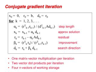
Procedure for analysis of beams through CBM • Procedure for analysis • 1. Construct the conjugate beam with the M/EI loading. Remember when the M/EI diagram is positive the loading is upward and • when the M/EI diagram is negative the loading is downward. • 2. Use the equations of equilibrium to solve for the • reactions of the conjugate beam. • This may be difficult if the moment diagram is complex.
Procedure • 3. Solve for the shear and moment at the point or points • where the slope and displacement are desired. • If the values are positive, the slope is counterclockwise and the • displacement is upward.
The following procedure provides a method that may be used to determine the displacement and slope at a point on the elastic curve of a beam using the conjugate-beam method. • Conjugate beam • Draw the conjugate beam for the real beam. This beam has the same length as the real beam and has corresponding supports as listed above.
In general, if the real support allows a slope, the conjugate support must develop shear; and if the real support allows a displacement, the conjugate support must develop a moment. • The conjugate beam is loaded with the real beam's M/EI diagram. This loading is assumed to be distributed over the conjugate beam and is directed upward when M/EI is positive and downward when M/EI is negative. In other words, the loading always acts away from the beam.[
Equilibrium[ • Using the equations of statics, determine the reactions at the conjugate beams supports. • Section the conjugate beam at the point where the slope θ and displacement Δ of the real beam are to be determined. At the section show the unknown shear V' and M' equal to θ and Δ, respectively, for the real beam. In particular, if these values are positive, and slope is counterclockwise and the displacement is upward
EXAMPLE & SOLUTIONS
Example Draw the shear and moment diagrams for the beam shown in Fig. The support at B settles 1.5 in. Take E = 29(103) ksi, I = 750 in4. 20 k 1.5 in A C B 12 ft 12 ft 24 ft Actual Beam
Solution Principle of Superposition • The beam is first degree statically indeterminate. • The centre support B is chosen as redundant, so that the roller at B is removed. 20 k 1.5 in A C Actual Beam B 12 ft 12 ft 24 ft
20 k 1.5 in A C • Byis assumed to act downward on the beam. Actual Beam B = 20 k B A C Primary Structure ΔB + By B Redundant By applied A C Δ’BB=ByfBB
Compatibility Equation • With reference to point B, using units of ft, we require • Use conjugate beam method to compute ΔB and fBB since the moment diagrams consists straight line segments. • For ΔB 20 k B A C 20 k A C 15 k 5 k 12 ft 36 ft
20 k A C Compatibility Equation 15 k 5 k 12 ft 36 ft 16 ft 8 ft 24 ft conjugate beam
Compatibility Equation 16 ft 8 ft 24 ft MB’ VB’ 8 ft 16 ft
1 k B A C Compatibility Equation • For fBB 1 k A C 0.5 k 0.5 k 24 ft 24 ft conjugate beam 24 ft 24 ft
conjugate beam Compatibility Equation • For fBB 24 ft 24 ft mB’ vB’ 24 ft 8 ft
Compatibility Equation • Substituting these results into eq. (1), we have • Expressing the units of E and I in terms of k and ft, we have
Equilibrium Equations • The negative sign indicates that By acts upward on the beam. 20 k A C By=5.56 k Cy Ay 12 ft 12 ft 24 ft
Equilibrium Equations 20 k A C By=5.56 k Cy=2.22 k Ay=12.22 k 12 ft 12 ft 24 ft
20 k • Using these results, shear and moment diagrams are A C By=5.56 k Cy=2.22 k Ay=12.22 k 12 ft 12 ft 24 ft V (k) 12.22 x (ft) -2.22 -7.78 -20
20 k • Using these results, shear and moment diagrams are A C By=5.56 k Cy=2.22 k Ay=12.22 k 12 ft 12 ft 24 ft M (k.ft) 146.7 53.3 x (ft)
Advantages of this method over others methods • Generally, the is a more direct and effective method than the consistency method in determining reactions and deflections of beams.
References: • Rc hibler , 2009 edition
Be calm Guys , feel free to ask any questions …. We are here ,to satisfy U ….. But one by one :P