Download
1 / 20
350 likes | 812 Vues
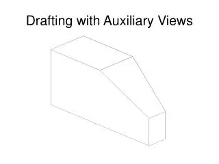
ARCHITECTURAL DRAFTING -Types of Views- -Basic House Construction-. Prepared by: Ms. Payne Adjunct Instructor. Floor plan – sliced about 4’ above floor. Elevations. Front, side and rear views (North-South-East-West)

E N D
ARCHITECTURAL DRAFTING-Types of Views--Basic House Construction- Prepared by: Ms. Payne Adjunct Instructor
Elevations. • Front, side and rear views (North-South-East-West) • Variety of lineweights can be used for more beautiful drawings. This type might use grayscale.ctb plot setting for shading variations.
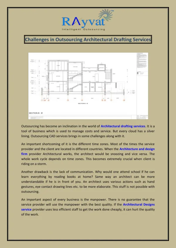
An Elevation is in front of the object; a Section slices THROUGH it
Section Cut Symbol – has a direction, and gives cross reference to the sheet it’s on
An Elevation is in front of the object;a Section slices THROUGH it
Section Drawings • Varying line weights for clarity
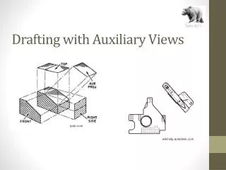
PLANS (‘TOP VIEW’)SECTION (‘vertical’ CUT)ELEVATION (SIDE VIEW) VIDEO http://www.manufacturinget.org/tag/orthographic-projection/
Orthographic views If you don’t use a book, at least TAKE NOTES. Hardly anyone can remember it all Also remember you can use the Ribbon to hover over a tool for brief description
Elevation Drawings (side, front, rear views) are a type of Parallel Projection Drawing.Unlike a Perspective, measurements are “true”
Typical Drawing Order • Cover Sheet – Code Notes • Site Plan • Floor Plan(s) • Reflected Ceiling Plan(s) • Building Sections • Elevations • Wall Sections • Details • Interior Elevations & Details, Tile pattern enlarged plans, etc. • Structural (Foundation & Framing Plans, Details) • Mechanical (HVAC, Plumbing) • Electrical/Lighting
Elevation drawings AutoCAD drawing using “Color + Lwt by Object.ctb” plot
Combined color CAD + jpgs or use Adobe Illustrator to color a B&W CAD dwf.
Wood Framed House Construction • Truss Roof • Stud walls • Sheathing = plywood or OSB sheets
Foundations • Foundation walls similar to the system in Draft 224 Project, show in-ground concrete piers below the floors and the perimeter concrete stem wall. • The footing is buried. • The next step is to lay wood joists across the concrete stem walls, with some posts sitting on the concrete piers also supporting wood beams. • They leave this space below the joists as a crawl space in case someday someone needs to repair plumbing below the floor. • In this one you can also see some other concrete slabs for the garage and porch, which we don’t have in the Draft 224 house.
Typical U.S. Light Construction: • Roof Trusses. Notice the crane to life them in place! • Wood Stud Framing with OSB sheathing (Oriented Strand Board, used in place of plywood for most walls) • ‘Flashing’ around window openings
Roof Trusses Almost all mass produced residential and light commercial buildings in the US use prefabricated wood trusses to span the roof. These are trucked in and lifted in place. They are made up of mostly 2x4’s fastened together. The walls are 2x6 wood studswith OSBsheathing.
Section cut perpendicular through trusses and joists (DRAFT 224 Class assignment cuts facing them)