Drafting with Auxiliary Views
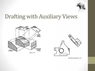
Drafting with Auxiliary Views. tpub.com. wikihelp.autodesk.com. Objectives. Create an auxiliary view from orthographic views Draw folding lines or reference-plane lines between any two adjacent views Construct depth, height, or width auxiliary views

Drafting with Auxiliary Views
E N D
Presentation Transcript
Drafting with Auxiliary Views tpub.com wikihelp.autodesk.com
Objectives • Create an auxiliary view from orthographic views • Draw folding lines or reference-plane lines between any two adjacent views • Construct depth, height, or width auxiliary views • Produce views to show the true length of a line, point view of a line, edge view of a surface, and true size view of a surface
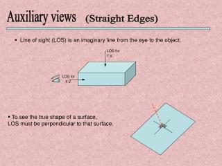
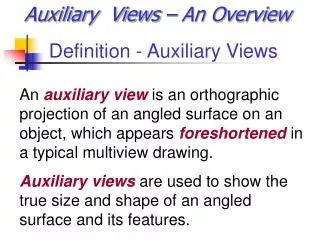
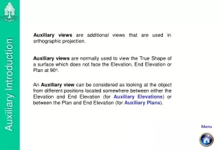
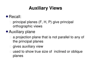
Why do we need auxiliary views? • To show information that is unavailable in other views • To show parts of the object in its true size and shape. (E.g. inclined surfaces) Understanding Auxiliary Views • An auxiliary view is an orthographic view that is not a standard projection • Auxiliary views allow principal faces of features that are not parallel to the standard planes of projection to appear true shape and size
Primary Auxiliary Views • A primary auxiliary view is projected onto a plane that is perpendicular to one of the principal planes of projection and is inclined to the other two
Classification of Auxiliary Views • Auxiliary views are named for the principal dimension shown in the auxiliary view such as: • Depth auxiliary • Height auxiliary • Width auxiliary
GETTING TO KNOW REFERENCE PLANES • Instead of using one of the planes of projection, reference planes parallel to the plane of projection and touching or cutting through the object are used in auxiliary views • Reference planes should be positioned so it is convenient to transfer distances • Reference lines, like folding lines, are always at right angles to the projection lines between the views • Measurements are always made at right angles to the reference lines or parallel to the projection lines • In the auxiliary view, all points are at the same distances from the reference line as the corresponding points are from the reference line in the alternate view, or the second previous view
Reference Planes Pearson Education 2009/Technical Drawing 13th Ed.
Hidden Lines in Auxiliary Views • Generally hidden lines should be omitted in auxiliary views unless they are needed to clearly communicate the drawing’s intent Pearson Education 2009/Technical Drawing 13th Ed.
Getting Started… this is what we will be doing…. • Examine the views, and choose the plane to project in its edge view. • Draw a reference/fold line parallel to the edge view of the inclined surface and at a convenient distance from it • In the front view, draw a light construction line at right angles to the inclined surface • From all points in the front view, draw projection lines at right angles to the inclined surface • Transfer the depth dimensions • Use the adjacent view to visualize where to darken final lines. • Use the projected lengths and depths via the adjacent views to determine the true size and shape of the object.
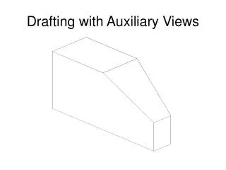
Start by finding the surface we will be projecting in its edge form. This is true length.
Start by determining the surface that needs projecting in its edge view. Then create a reference (fold) line. This line can be used to start the auxiliary view. Remember to create the line in an open area where the added view will not conflict with other views.
From the reference line, measure over the needed widths(Remember… the lengths are already determined by the projection lines). Using the measurements from the adjacent view, from the reference line, measure 0.52 and draw a construction line. Then do the same for the 1.12, 1.42 and the overall width line at 1.80. Total Width 90o From each relative point, Draw a construction line that extends from the surface at 90 degrees (a right angle). Extend it long enough to accommodate for the width of the surface.
Once you have created all the lengths and widths, use the adjacent view to visualize the shape. Here it is similar to a “S”. Use the construction lines and their intersections to determine points. Darken as needed. Because the surface is projected at a right angle from the true length edge, you now have a surface projection that is seen in true size and shape.
Seeing is believing… This is not a proper technique, it is just to show you that our size and shape are verified.
REVIEW tpub.com