Chapter 9 Auxiliary Views and Editing with GRIPS
120 likes | 545 Vues
Chapter 9 Auxiliary Views and Editing with GRIPS. Learning Objectives: Use 2D Projection method to draw Auxiliary Views. Create Rectangles. Use the basic GRIPS Editing commands. Create and Edit the Plot Style Table. Set up and use the Polar Tracking option.

Chapter 9 Auxiliary Views and Editing with GRIPS
E N D
Presentation Transcript
Chapter 9 Auxiliary Views and Editing with GRIPS Learning Objectives: • Use 2D Projection method to draw Auxiliary Views. • Create Rectangles. • Use the basic GRIPS Editing commands. • Create and Edit the Plot Style Table. • Set up and use the Polar Tracking option. • Create multiple Viewports in Paper Space.
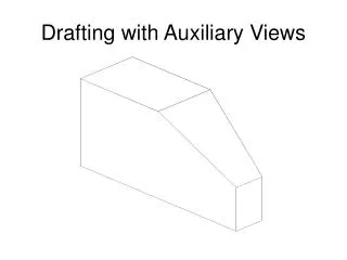
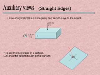
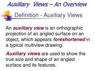
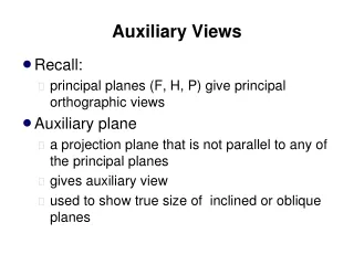
Introduction Many designs have features located on inclined surfaces that are not parallel to the regular planes of projection. To truly describe the feature, the true shape of the feature must be shown using an auxiliary view. An auxiliary view has a line of sight that is perpendicular to the inclined surface, as viewed looking directly at the inclined surface. An auxiliary view is a supplementary view that can be constructed from any of the regular views. Standard Views Auxiliary View
Orthographic Projection No matter what the position of a surface may be, the fundamentals of projecting a normal view of the surface remain the same: The projection plane is placed parallel to the surface to be projected. The line of sight is set to be perpendicular to the projection plane and therefore perpendicular to the surface to be projected. This type of view is known as normalview. In the figure below, the design has an inclined face that is inclined to the horizontal and profile planes and perpendicular to the frontal plane.
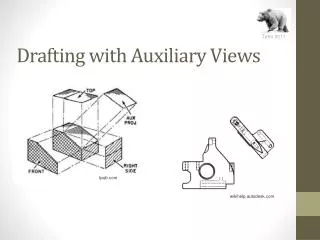
Folding Line Method The folding-line method uses the concept of placing the object inside a glass-box, the distances of the object to the different projection planes are used as measurements to construct the necessary views, including the auxiliary views.
Using the AutoCAD Classic Workspace Workspaces are sets of menus, toolbars, palettes, and ribbon control panels that are grouped and organized so that a user can work in a custom, task-oriented drawing environment. Three task-based workspaces are pre-defined in AutoCAD 2D Drafting & Annotation: drawing environment set for 2D drafting tasks. 3D Basics: drawing environment set for Basic 3D modeling tasks. 3D Modeling: drawing environment set for Advanced 3D modeling tasks. AutoCAD Classic: the classic drawing environment set for 2D tasks. This environment provides the most drawing area on the screen.