Auxiliary Views
Auxiliary Views. Chapter 7. Overview. Revolution. Auxiliary. Revolved. Normal Views vs. Auxiliary Views. Normal. Auxiliary. Basic Relationship of the Auxiliary Plane to the Normal Planes. Example. Anchor with a slanting surface. Normal. Auxiliary. Example . Simple Inclined Wedge.


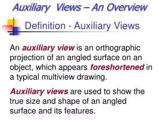
Auxiliary Views
E N D
Presentation Transcript
Auxiliary Views Chapter 7
Overview Revolution Auxiliary Revolved
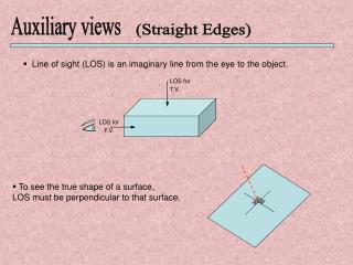
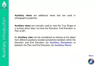
Normal Views vs. Auxiliary Views Normal Auxiliary
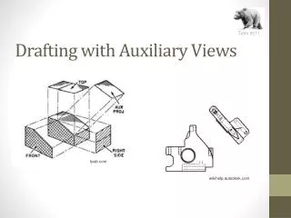
Basic Relationship of the Auxiliary Plane to the Normal Planes
Example Anchor with a slanting surface
Normal Auxiliary
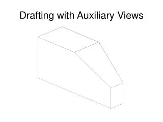
Example Simple Inclined Wedge
Primary Auxiliary View Front Auxiliary
Primary Auxiliary View Top Auxiliary
Primary Auxiliary View Right-Side Auxiliary
1. Create the front and side views and a partial top view, as shown in Figure A. Do not dimension the views.
2.Create a construction line perpendicular to the line that represents the inclined plane at the lower end of the inclined line in the front view. To do this, pick the two endpoints of the short end line, as shown in Figure B.
3. Copy the construction line to each important point in the front view. See Figure C.
4.Copy the inclined line to another location on the construction lines, as shown in Figure D. Use the Nearest object snap to ensure that the endpoint of the inclined line is exactly on the lowest construction line.
5. Offset the line you created in step 4 to the right by the depth dimension, .76, as shown in Figure D. This defines the depth of the object in the auxiliary view.
6. Trim the construction lines to form the other boundaries of the auxiliary view. Use the Layer Control above the drawing area to move the lines to their appropriate layers: Hidden, Centerline, etc. See Figure E.
7. Add the other centerline, the hole, and other details based on the dimensions given in Figure A above. The finished drawing should look like the one in Figure F.