Learn Engineering Views in Multiview Drawings with Fold Line Method
Understand how to generate views showing inclined and oblique surfaces in true shape, using successive rotations. Topics include definition and use of auxiliary views, principles, fold line method, and projection planes.

Learn Engineering Views in Multiview Drawings with Fold Line Method
E N D
Presentation Transcript
Auxiliary Views Engineering II
Objective • To understand how to generate views that show inclined and oblique surfaces in true shape in multiview drawings • To better understand the manipulation of 3-D objects using successive 90 degree rotations in preparation for solid modeling
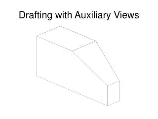
Outline • Definition and Use • Fold Line Method • Primary Auxiliary Views • Review of descriptive geometry • Example: Inclined surface
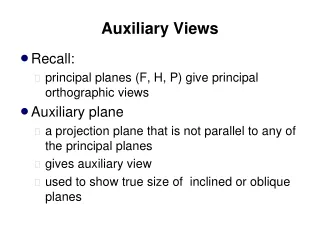
Auxiliary Vs. Principle Views • Principle planes • Horizontal (Top and bottom view) • Frontal (Front and back view) • Profile (Left and right side view) • Auxiliary views • Definition: An orthographic view that is projected into a plane that is not parallel to any of the principle planes • Purpose: To show the true shape of a detail that does not lie in on of the principle planes
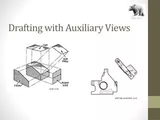
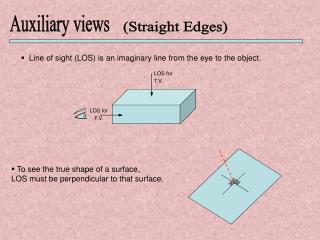
Review: Fold Line Method • A fold line (hinge) may be placed between adjacent views to aid in the construction and interpretation of multiview drawings • Projection lines are always perpendicular to fold lines • The distance from a fold line to any specific point on an object is the same for any related views (ex. top and side view) • Fold lines represent a 90 degree rotation in viewpoint
Example: Fold Line Method • Distances from the fold line in View A are equal to the distance from the fold line in View C • Follow projection lines to keep track of vertices • Use offset when creating View C from View A & B • Note that the projection lines are always perpendicular to fold lines.
Primary Auxiliary View • Definition: Any view that is projected from (adjacent to) one of the principle views and which is not parallel to any of the principle planes • A primary auxiliary view is perpendicular to only one of the principle planes • Any inclined surface may be shown in true shape in the appropriate primary auxiliary view • If the fold line for an auxiliary view is parallel to the edge view of an inclined surface the inclined surface will appear in true shape in the auxiliary view
Example: Primary Auxiliary Views • Use the UCS command to rotate about the Z axis and align the x axis up with the inclined surface • Project perpendicular projection lines from the inclined surface (ORTHO) • Determine the depth of each point from related views (OFFSET) • Use DDOSNAP to quickly select features
Projection Planes • A fold line represents the projection plane for the adjacent view • A line appears true length if it lies in a plane parallel to the projection plane • A line which is not parallel to the projection plane appears foreshortened • A line which is perpendicular to the projection plane appears as a point
Lines • A line which is parallel to a fold line will appear true length in the adjacent view • A true length line which is perpendicular to a fold line will appear as a point in the adjacent view • Line 1-3 is parallel to the fold line in the right side view and true length line in the front view • Line 1-2 is true length in the right side view and is a point in the front view
Lines • All views adjacent to a point view of a line will show the line in true length • A line which does not appear true length in any of the principle views is called an oblique line
Surfaces • A Surface appears in “true shape” (undistorted) if it is parallel to the projection plane • A surface appears as an edge parallel to the fold line in all views adjacent to the true shape view of the surface • If any line on a surface appears as a point then the surface will appear as an edge • A surface which does not appear as an edge in any of the principle views is called an oblique surface
Memorize These Statements Before The Quiz • A fold line that is parallel to a line gives a view that shows the “true length” of the line • A fold line that is perpendicular to a “true length” line on a surface gives a view that shows the surface as an edge. • A fold line that is parallel to the edge view of a surface gives a view that shows the “true shape”
Helpful Visualization Tools • Label surfaces • Label vertices - List nearest vertex first at each location (1,2) • Follow construction lines to determine location • Equal number of sides - A surface with 3 sides will have three sides in every view • Parallel edges - If lines are parallel in one view they will be parallel in every view