Download
1 / 1
10 likes | 95 Vues
Study on MPPC damage by C6+ ion beam irradiation at HIMAC accelerator, measuring output decrease after exposure. Includes leak current measurement post-irradiation and comparison of two MPPC types.

E N D
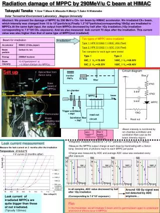
Radiation damage of MPPC by 290MeV/u C beam at HIMAC 100C_1 100C_2 50C_1 50C_2 Bias72.0V Bias70.0V Bias70.0V Bias72.0V Method Takayuki Tanaka Y.Itow T.Mase K.Masuda H.Menjo T.Sako H.Watanabe Solar Terrestrial Environment Laboratory ,Nagoya University Abstract: We present the damage of MPPC by 290 MeV/u C6+ ion beam by HIMAC accelerator. We irradiated C6+ beam, which intensity was changed from 10 to 107(particle/s).Finally 1.2*1010particles(corresponding 16kGy) are irradiated to MPPCs.At the same light input, the output from MPPCs decreased by half after 1Gy irradiation.(1Gy irradiation corresponding to 7.5*105 C6+ exposure). And we also measured leak current 70 days after the irradiation. This current value was also higher than that of same type of MPPC(not irradiated) Two types of MPPC were irradiated Type 1: HPK S10362-11-050C (400 Pixel) Type 2: HPK S10362-11-100C (100 Pixel) Two samples for each type were tested Type 1 Type 2 50C_1 V0=70.59V 100C_1 V0=69.59V 50C_2 V0=69.55V 100C_1 V0=69.48V Beam for irradiation Irradiation! Set up Circuit diagram Optical fiber from Xenon lamp Bias V monitor PMTs Xe lamp filter Base board of MPPCs 47kΩ ion chamber C ion beam line 9.6nF 47kΩ MPPC collimater beam line 9.6nF MPPC Trigger scintillator + PMT 10kΩ thermometer read out circuit Boxes including read out circuit Scintilation fiber + PMT Read out • Beam intensity is monitored by ion chamber,scintillator and scintilation fiber.(use as the beam intensity region) Bias V supply ADC CAMAC 2249W(LeCroy) • Integrated irradiation reached at 1.2*1010 particles (corresponding to 16kGy) • Measure the MPPCs output charge at each dose by illuminating with a Xenon lamp. Several tens of photons reach to each MPPC per pulse. • Charge was measured by ADC and average ADC value was evaluated every after exposure Takasago TPO120-06D Leak current measurement Measure the leak current on 2 months after the irradiation Temperature :21±0.2 ℃ I-V curve (2 months after) Current (uA) In all samples, ADC value decreased by half after 1Gy irradiation (Corresponding to 7.5*105 exposure ) Around 100 Gy signal was not detected by ADC anymore… Bias voltage(V) Leak current of irradiated MPPCs are quite bigger than these of not irradiated. (Tipically 10times) Plan In this November, we will irradiate C beam and Co gamma beam again to understand what kind of effects occur in MPPCs.