MeRHIC multiple cathode design
This paper presents a comprehensive design for a multiple cathode electron beam system optimized for beam quality and efficiency. Key parameters include a bunch charge of 5nC, average current of 50mA, and transverse emittance of less than 70 mm.mrad. The configuration integrates advanced components such as a Gatling gun, third harmonic cavity, and ballistic compression techniques, ensuring high energy spread and optimal performance at 10MeV. Preliminary simulation results validate the design, indicating strong potential for achieving required beam specifications.

MeRHIC multiple cathode design
E N D
Presentation Transcript
MeRHIC multiple cathode design Xiangyun Chang, I. Ben-Zvi, D. Kayran, V. Litvinenko, V. Ptitsyn, J. Skaritka, E. Wang, G. Wang, Q. Wu
Beam requirements • Bunch charge: 5nC • Average current: 50mA • Transverse emittance: <70mm.mrad • Final bunch length (rms): <3mm • Energy spread @ 10MeV: ~1%
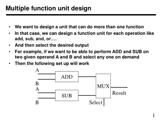
System configuration Gatling gun 3rd harmonic cavity Spin rotator bunching cavity Ballistic compression Booster linac α 130cm 60cm 30cm 60cm 210cm Combiner
HV feedthrough Assembly chamber Combiner Transport train Laser ports Vacuum port By John Skaritka
Solenoids: 5cm550G Bending magnets: 600cm.Gauss
Cathode R=3cm Epeak=10.3MV/m Ecathode=4.3MV/m @ 250kV 1.6cm Electron beam emission area 30 deg Gap=3cm
Gatling gun 3rd harmonic cavity Spin rotator bunching cavity Ballistic compression Booster linac α Combiner Scenarios
Parameters in simulation • Cathode: • Cathode size: 1cm dia. • Emission area: 0.8cm dia. • Gap: 3cm • Voltage: 150~250kV • Bunch Charge: 5nC • Laser: • Transverse uniform • Longitudinal Gaussian: 0.5~1ns • Peak current density=20A/cm2 @ σ=0.5ns • Peak current density=10A/cm2 @ σ=1ns • 20A/cm2 was demonstrated (SLAC_SLC, 120KV) • Solenoids: • I.D./O.D./Length: 2cm/4cm/5cm • Field: 550G • Bending magnets: • FieldLength: 600cm.Gauss • Final energy:10MeV
Before bunching cav. After bunching cav. Before Linac After Linac
Conclusions • The present optimized deflection angle is 20deg. • Beam quality is strongly related to HV. 250kV or higher is desired. • Longer initial bunch (1ns) with lower RF frequency cavities gives better results. • Ballistic compression is the most effective way compressing the bunch at this energy level. • This preliminary simulation has given us confidence of achieving the required beam.