Download
1 / 19
190 likes | 350 Vues
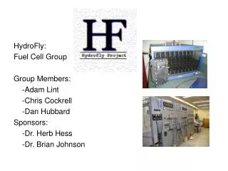
HydroFly: Fuel Cell Group Group Members: -Adam Lint -Chris Cockrell -Dan Hubbard Sponsors: -Dr. Herb Hess -Dr. Brian Johnson. HydroFly: Flywheel Group Group Members: -Gavin Abo -Nate Stout -Nathan Thomas. Two Groups: -Flywheel -Fuel Cell.

E N D
HydroFly: Fuel Cell Group Group Members: -Adam Lint -Chris Cockrell -Dan Hubbard Sponsors: -Dr. Herb Hess -Dr. Brian Johnson
HydroFly: Flywheel Group Group Members: -Gavin Abo -Nate Stout -Nathan Thomas Two Groups:-Flywheel-Fuel Cell
Design Review II:Final Design Review Outline • Project Objectives • Project Introduction • Project Status • Design Description and Functionality -DC/DC Converter -Inverter -Transformer -Control -Software -Zero Crossing Detection • Schedule • Budgeting • Questions
Primary Objectives-Interface a Fuel Cell to the AMPS. -Provide power to the AMPS
Secondary Objectives -Produce an Operation Manual -Protect the Fuel Cell and Interface -User Safety
Introduction Why are we interfacing the Fuel Cell to the Analog Model Power System? -Alternative Energy Source -Flexibility for the AMPS
Functional Specs The specifications for the interface are the following: • 18-36V DC input from the Fuel Cell • Output 208 +/- 2 % V AC (L-L 3-phase) • Output Voltage at 60Hz +/- 0.05Hz • Max power flow of 200W for the interface
Overall System Layout -DC/DC Converter -Inverter -Transformer -Control -Software -Zero Crossing Detection
Overall System Layout -DC/DC Converter -Inverter -Transformer - Control -Software -Zero Crossing Detection
Control What does the Control do? -Produces PWM -Synchronizes AC Systems -Controls Power Flow -Protects Fuel Cell and Interface -Monitors Zero Crossings -Calculations
How are these tasks accomplished? -DSP TMS320LF2401A TI
PWM Seven 16-Bit Pulse-Width Modulation (PWM) Channels Which Enable: - Three-Phase Inverter Control
Synchronize AC Systems -Magnitude -Frequency -Phase/Zero Crossings (30 degrees ahead)
Power Flow P = |Vfc||Vamps|sin(δ) X L=181 mH Q = |Vfc||Vamps|cos(δ) X -|Vamps|^2 X
Protects Fuel Cell and Interface Checks for undesired operation conditions -PW on Zero Crossing -Frequency variation -Voltage differences
Other DSP tasks -Monitors Zero Crossings -Calculations
Overall System Layout -DC/DC Converter -Inverter -Transformer -Control - Software -Zero Crossing Detection