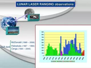
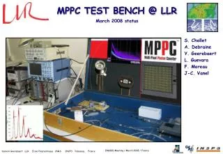
MPPC TEST BENCH @ LLR
S. Chollet A. Debraine Y. Geerebaert L. Guevara F. Moreau J-C. Vanel. MPPC TEST BENCH @ LLR. March 2008 status. MP P C : Multi-Pixel Photon Counter. What do we have to measure ? Reverse current vs Vop & T° (Vbr+ Δ V) Gain vs Vop & T° Dark Noise Rate vs Vop & T°

MPPC TEST BENCH @ LLR
E N D
Presentation Transcript
S. Chollet A. Debraine Y. Geerebaert L. Guevara F. Moreau J-C. Vanel MPPC TEST BENCH @ LLR March 2008 status
MPPC : Multi-Pixel Photon Counter • What do we have to measure ? • Reverse current vs Vop & T° (Vbr+ΔV) • Gain vs Vop & T° • Dark Noise Rate vs Vop & T° • Photo detection efficiency P.D.E. (relative to PMT) Where do we find those information with new packaging ?
20 dB Attenuator Testbench Setup • Setup for calibration (orange) and MPPC Parameters measurement (Blue) • Data from Source Meter : • Ireverse=f(Vop) • Data from oscilloscope : • GAIN : Histograms of integrated pulses (in the dark, with few photoelectrons & calibration) • DNR : V=f(t) during 2 ms. (1ns/sample) • PDE relative to PMT Trigger on: pulse in the dark LED pulse generator Calibration pulse generator Dark box Ambient temperature measurement High Voltage PM Tube Source meter Vpol OPTICAL FIBERS LED Pulse generator GPIB 10 KΩ BLUE LED I=f(V) 100 nF Oscilloscope 1 GHz, 10 Gs/s MPPC Calibration Pulse generator C 68.4 pF Voltage Amplifier 0 to 12 dB Attenuator Gain 38.5 dB BW 1 GHz Trigger (or trigger on signal it-self)
Automatic reverse current measurement I=f(Vop) • Data from Source Meter : • Ireverse=f(Vop) • Determine normal/geiger mode limit: • Define a Vop range for next measures • Measure leakage current in normal mode
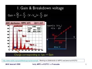
MPPC Gain measurement • Gain = Qin/1.6 10-19 Correspond to 1 photoelectron peak • Qin = <peak@1p.e.> V.ns / Calibration V.ns/e- • Measured Gain = 7.67E+05 • To be compared with value on MPPC bag M=7.50E+05
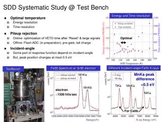
MPPC dark noise rate (DNR) measurement • From V=f(t) records, counting the number of pulses above a given threshold A view of stacked pulses DNR 350 KHz (value on MPPC Bag : 378 kHz) Optical Crosstalk : 25 kHz (value on MPPC Bag : 25 kHz) Counting rate (kHz) Number of Pulses in 1 record (2ms) Threshold (mV)
LLR MPPC Test bench • What have changed since November 2007 ? • PDE measurement • Measurements @ LAL • Validation for different parts of final test bench • Measurements with LAL Readout ASIC • FPGA evaluation board • Communication with PC for automation • Light distribution design • Design of final test bench setup • Actual design • What is done • To-do list
PDE Measurement (relative to PMT) • Setup for Photo detection efficiency measurement • Data from oscilloscope : • PDE : MPPC integrated pulse divided by PMT integrated pulse Trigger on: LED pulse generator Dark box Ambient temperature measurement High Voltage PM Tube Source meter Vpol OPTICAL FIBERS LED Pulse generator GPIB 100 KΩ BLUE LED I=f(V) 100 nF Oscilloscope 500 MHz, 5 Gs/s MPPC Gain 38.5 dB BW 1 GHz Voltage Amplifier Trigger
Measurements @ LAL • To crosscheck with our data, measurements for 3 MPPC (2x 100pix & 1x 400pix) have been done by LAL instrumentation group (N. Dinu).
LLR MPPC Test bench • What have changed since November 2007 ? • PDE measurement • Measurements @ LAL • Validation for different parts of final test bench • Measurements with LAL Readout ASIC • FPGA evaluation board • Communication with PC for automation • Light distribution design • Design of final test bench setup • Actual design • What is done • To-do list
Test of Sipm readout ASIC from LAL • Setup for MPPC gain measurement Dark box Ambient temperature measurement Source meter Vpol LED Pulse generator 10 KΩ BLUE LED 100 nF Oscilloscope 1 GHz, 10 Gs/s MPPC LAL ASIC 50 Ω 100 nF Trigger
Test of Sipm readout ASIC from LAL • Evaluation of Sipm readout chip from LAL with a 400 pixels MPPC. Power supply Oscilloscope Source Meter MPPC is in the dark box LED pulse generator T° measurement LAL Sipm ASIC evaluation board FPGA for ASIC control
Test of communication between FPGA, PC and ASIC • We will use a simple FPGA evaluation board to control ASIC, interface with instruments and communicate with PC. Interface with instruments trigger, trigger enable, etc… Slow control Communication with PC (RS232) ASIC control Select channel, gain, shaper, etc…
Design of light distribution • One LED to 36 MPPC with 36 fibers • Same length, same path for each fiber • Same light intensity at the beginning of each fiber • 2 light diffusion layers Noise events/total number of events
Pulse Generator T° Monitor Source Meter FPGA Eval. board INGRID DB Device LOG GUI MPPC Test bench Eth. 1 GPIB RS485 RS232 Eth. 2 Test BenchApplication PyMySQL Web Browser
Design of final test bench • General view of final test bench
Mechanical view of MPPC Test bench • Front-end electronic • MPPCs • T° sensors • Fibers • Light diffusion layers • Blue LED A. Cauchois A. Bonnemaison
“Support_MPPC” board • Design of board “support_MPPC” (6 PCBs are foreseen for 4 April). • 2 layers, • minimal gap : 150 µm • Thickness : 3.2 mm • 50 Ω coplanar waveguide design for MPPC signals • Mechanical accuracy of +/- 0.05 mm all over the board • Will hold 72 HOLTITE socket
To-do list • Design of SAKE board (Sipm Analyzer for a Kamiokande Experiment) • Mother board (support MPPC is daughter board) • 2 Sipm ASICs • 36 relays to switch on/off HV for I reverse measurement • Interface with FPGA board • foreseen to be at LLR in May • Debug hardware electronic • Writing VHDL code for the automation of the test bench • Finalize the mechanical design, machining all parts of the test bench • Calibration of entire system • MPPC production test