Download
1 / 33
340 likes | 501 Vues
SDR Test bench Architecture. WINLAB – Rutgers University Date : October 15 2009 Authors : Prasanthi Maddala, prasanthi.m@gmail.com Khanh Le, kle@winlab.rutgers.edu. SDR platform – V1.0.

E N D
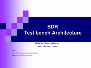
SDR Test bench Architecture WINLAB – Rutgers University Date : October 15 2009 Authors : Prasanthi Maddala, prasanthi.m@gmail.com Khanh Le, kle@winlab.rutgers.edu
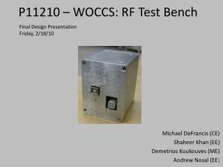
SDR platform – V1.0 • The Figure above shows the first version of SDR platform and this document describes a test bench being developed for it. SDR Test Bench
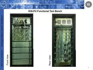
SDR Test Bench • This Figure shows a test bench for an SDR design. • The test bench could contain different drivers and monitors controlled by the simulation manager as shown in the figure, depending on the design under test. • Our current version of test bench provides an Ethernet driver, a DiBo SPI monitor, a WiBo control monitor, and a simulation manager that interacts with these blocks. SDR Test Bench
Ethernet Driver • Ethernet driver emulates the Ethernet receive PHY. SDR Test Bench
Ethernet Driver • On receiving a signal from the simulation manager along with the data to be sent, Etherner driver sends data to the receive Ethernet interface in the SDR design. • It can be either set to 100 Mbps or 1Gbps through the generic DATA_RATE • It can also add Ethernet and IP headers, or Ethernet header alone (depending on the signal add_hdr), before sending out data to the design under test. SDR Test Bench
Ethernet Driver – SDR Design Interface SDR Test Bench
Ethernet Driver – Simulation Manager Interface SDR Test Bench
Ethernet Driver – Commands SDR Test Bench
Monitors • Monitors provided in this design are • DiBo SPI Monitor • WiBo Control Monitor which consists of • 1. WiBo SPI Monitor • 2. U2 Monitor • 3. Antenna Switch Monitor - Antenna Switches are treated as a register by introducing a dummy ant_sw_sync signal which is used only for simulation purposes. • Each of the above is used to monitor a set of registers (SPI registers, u2 , antenna switches) and they use a common block called the register monitor. Register monitor keeps a record of register contents and register write operations with the help of text files. It can also take various commands from the simulation manager, such as comparing all the register contents with the values given in a text file, comparing a particular register value etc., and send a response back to the simulation manager. • Following slides explain the register monitor first, and then discuss how each of the above monitors uses the register monitor to perform the required function. SDR Test Bench
Register Monitor SDR Test Bench
Register Monitor – Register read/write interface SDR Test Bench
Register Monitor – Simulation Manager Interface SDR Test Bench
Register Monitor – Commands SDR Test Bench
Register Monitor – Files • Register Log File – The register monitor logs all its read/write operations in the this file. A register log file can look as follows • No Rd/Wr Register No Register Data • ************************************************************************************* • 1 Read 0 00010010 • 2 Write 0 00011110 4 Write 4 01010101 • Register Content File – Register monitor keeps a record of the register contents in this file. • The initial contents are by default all 0s, but they can be non-zero too. Every write operation results in updating this file and for every read operation, register data is fetched from this file. It can look as follows • Register No Register Data • ************************************************************ • 0 01101000 • 1 00000000 • 2 01010000 • Error File - Read/write errors(Ex: Invalid register no, read not supported ), command failures are logged in the error file. The error file may look like this • Operation Number Error • ********************************************************************************* • Read 3 Invalid register no : 68 • sim_mgrcmd 2 Bad Command code 00011111 SDR Test Bench
SPI Monitor • An SPI monitor consists of an SPI emulator and a register monitor. • SPI emulator interprets the SPI input signals and performs register read/write operations. • Write operation corresponds to sending an update to the register update monitor, with the register address and data information. • Read operation corresponds to fetching register data from the register monitor, and sending out the data bits serially. • SPI emulator architecture depends on the actual chip that is being used (Ex MAX 2829 or AD9862). Though they have a standard 3 or 4-wire SPI interface, read/write operations are performed in a different way in each of the chips. SDR Test Bench
DiBo SPI Monitor • DiBo SPI monitor emulates the SPI interface and registers of AD9862. SDR Test Bench
DiBo SPI Monitor – SDR Design Interface SDR Test Bench
WiBo Control Monitor • WiBo control monitor emulates the following • - U2 – the shift register MM74HC595 • - SPI interface and registers on MAX2829 • - Antenna Switches U3, U4, U5 SDR Test Bench
WiBo Control Monitor SDR Test Bench
WiBo SPI Monitor • WiBo SPI emulator emulates the SPI interface and registers of MAX2829. • MAX2829 SPI is a 3-wire interface which does not support read operations. • It has 13 registers which are 14 bit wide as opposed to 64, 8 bit registers in AD9862. • Also, MAX2829 does not support dual word write operations as AD9862. • With these and other differences in operation, though the same interface is maintained (with sdo floating – three stated always) for WiBo spi monitor, its architecture is completely different. SDR Test Bench
WiBo SPI Monitor – SDR Design Interface SDR Test Bench
WiBo SPI Emulator – Register Monitor Interface SDR Test Bench
U2 Monitor SDR Test Bench
U2 Monitor – SDR Design Interface SDR Test Bench
U2 Emulator – Register Monitor Interface SDR Test Bench
Antenna Switch Monitor SDR Test Bench
Antenna Switch Monitor – SDR Design Interface SDR Test Bench
Antenna Switch Emulator – Register Monitor Interface SDR Test Bench
Simulation Manager SDR Test Bench
Simulation Manager • Simulation manager shown in the figure, has an interface that is defined to interact with Ethernet driver, DiBo SPI monitor, and WiBo control monitor. • This interface has to be modified if any more blocks like Ethernet monitor, RS232 driver etc., are added to the test bench • For a given interface, the simulation manager can have different architectures. • Ex: 2 designs that can be tested with this simulation manager • - test_v5lx_top.vhd • - ocrp_top.vhd • these designs can have different architectures for the simulation manager. SDR Test Bench
Simulation Manager – Architecture for OCRP • OCRP is designed such that all control is through Ethernet only i.e., SPI register writes, U2 and antenna switch updates can be done only through control commands sent over Ethernet. The simulation manager for OCRP does the following • takes an Ethernet command file and sends commands to the Ethernet driver. • After sending all the Ethernet frames, it sends a file compare command to all the monitors along with appropriate golden files. • Once it receives responses from the monitors, it reports them to the report file. SDR Test Bench
Simulation Manager – Files for OCRP • Ethernet Command File • Contains a list of command file names and the properties associated with these files. These properties can vary with the simulation manager (sim_mgr)architecture. • For OCRP, the following file format may be followed • Command Type Add Ethernet Header Add IP header File Name • **************************************************************************************************** • Cntrl Yes Yes wibo_freq_2_437.txt • Cntrl Yes Yes set_rx.txt • Data No No mod_data.txt • The test bench top file (tb_top.vhd) is instantiated with its ETH_CMD_FILE generic set to the Ethernet command file name. This is then passed down to the sim_mgr. • The sim_mgr reads data from each of the files in the list into an array of bytes and sends it to the ethernet driver along with a command and a param word. • ReportFile • The simulation manager logs all the commands that it sends and the responses obtained in this file. A report file may look as follows • ********************************************************************************************* • Ethernet driver command sent • ********************************************************************************************* • Check next update command sent to DiBo Monitor • ********************************************************************************************* • DiBo command pass • ErrorFile • The simulation manager reports any errors in simulation, by writing to this file… SDR Test Bench
Simulation Manager – Architecture for test_v5lx_top.vhd • Test_v5lx_top is the first SDR design, developed to test the SDR platform (v1.0). • This design does not take any data commands. It takes control commands with a fixed length – • Though WiBo and DiBo can be controlled through Ethernet, initial controls are sent by the design itself. • Whenever the design receives a control command, it updates all the registers on both DiBo and WiBo. • So, the simulation manager for test_v5lx_top does the following • 1) takes an Ethernet command file and drives the Ethernet driver. The Ethernet command file looks similar to that of OCRP, except that the command type field is not used. • 2) Waits for the first set of register updates before sending the first command to the Ethernet driver. • 3) After sending a command to the Ethernet driver, it waits for another set of register updates before sending the next command. SDR Test Bench