Download
1 / 8
80 likes | 101 Vues
This generic digitizer VME board features 12 channels with 16-bit resolution at 10MHz operation. It offers hardware and software onboard data processing, smart triggering, and a buffer with up to 500k samples per channel.

E N D
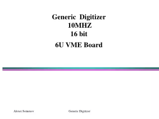
Generic Digitizer 10MHZ 16 bit6U VME Board Generic Digitizer
Futures • 12 channels, 16 bit at 6U VME Board • DC- up to 10MSPS Operation • Up to 500k sample per channel buffer • Hardware & Software onboard data processing • Smart triggering based on FPGA algorithm Generic Digitizer
10MHz,16bit 3 channels ADC 4 CHIPS Generic Digitizer VME BUS FPGA CYCLONE EP1C12240 State Machine Logic OR/AND NIOS Embedded Processor A n a l o g I n p u t s VME Drivers 4Mx32 SDRAM MT48LC4M32B2 JTAG 4 Mbit Serial Configuration Device EPCS4 EPCS4 Interface MAX7128 CLOCK IN 4 Mbit Serial FLASH Device EPCS4 CLOCK OUT GATE External Control TRIGGER TCLK SYNC IN SYNC OUT CRYSTAL 25MHz
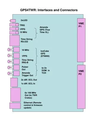
Digitizer Prototype LED s: Ready, VME, Gate, Trigger EXT Clock EXT Gate EXT Trigger SYNC TCLK VME DRIVER s HW Reset PreAMP s JTAG ADC s FPGA SDRAM 12 analog inputs 25MHz Crystal Mode Select SW Configuration Device HW Address Generic Digitizer
AD9826 16-Bit Signal Processor • Features • 16-Bit 15 MSPS A/D Converter • 3-Channel 16-Bit Operation up to 15 MSPS • 1-Channel 16-Bit Operation up to 12.5 MSPS • Correlated Double Sampling • 1~6x Programmable Gain • ±300 mV Programmable Offset • Input Clamp Circuitry • Internal Voltage Reference • Multiplexed Byte-Wide Output • Optional Single Byte Output Mode • 3-Wire Serial Digital Interface The AD9826 is a complete analog signal processor. It features a 3-channel architecture designed to sample and condition the outputs of color CCD arrays. Each channel consists of an input clamp, Correlated Double Sampler (CDS), offset DAC, and Programmable Gain Amplifier (PGA), multiplexed to a high-performance 16-bit A/D converter. Generic Digitizer
FPGA Design 3 channels x 4 = 12channels Data from ADC ADC Data Channels MUX Data MUX FIFO 512x16 Local BUS Arbiter & MUX SDRAM Interface SDRAM FIFO 512x16 Set ADC Mode, Gain, Offset FIFO 512x16 VME interface VME BUS ADC Serial Control interface Digitizer MODE Control TCLK Serial configuration Device Interface Gate Trigger Sync ADC CLOCK To EPCS4 Interface PLL Multiplier INT CLOCK 25MHz RF,53MHz Generic Digitizer
LabView Interface Generic Digitizer
STILL OPEN QUESTIONS • Channel to channel crosstalk is ~80dB at 10MHz from specification for AD9826. What is this ratio for a real board? And also, • What is a total ADC noise (3-9 LSB from spec) ? • What is a Integral and Differential Nonlinearity (16 and 0.5 LSB from spec)? Generic Digitizer