Download
1 / 21
220 likes | 370 Vues
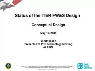
Status of the ITER FW&S Design. Conceptual Design May 11, 2005 M. Ulrickson Presented at PFC Technology Meeting At PPPL.

E N D
Status of the ITER FW&S Design Conceptual Design May 11, 2005 M. Ulrickson Presented at PFC Technology Meeting At PPPL Sandia is a multiprogram laboratory operated by Sandia Corporation, a Lockheed Martin Company,for the United States Department of Energy’s National Nuclear Security Administration under contract DE-AC04-94AL85000.
Outline • Shield Module • Physical layout • Thermal Analysis • Electromagnetic Analysis • First Wall • Physical layout • Thermal Analysis • Electromagnetic Analysis • Issues to be resolved
Shield Thermal Analysis • Temperature rise due to nuclear heating has been calculated with 3.6 W/cm3 • The temperature rise in the stainless is only due to nuclear heat • A delta T of about 16 C over 4 mm is sufficient to cause stresses of about yield in 316 LN Steel
Shield EM Analysis • A complete 20 degree sector of the vacuum vessel, ports, lower triangular support, module 18 and 17, and the divertor was constructed in OPERA. PF coils were included. TF simulated by a single wire. • Two disruption cases were provided by IT • An 18 ms exponential current decay vertical disruption • A 40 ms linear decay VDE
First Wall Thermal Analysis • The delta T across 10 mm of Be at 50 W/cm2 is 28C • The temperature rise in the Be and Cu due to nuclear heating is negligible. • At the normal operating point the Be has the capability of absorbing up to 18.4 J/cm2 without melting. • The temperature rise in the 316 LN is discussed earlier.
First Wall EM Analysis • A simplified model of the first wall was made for EM analysis while design details were worked out • Rectangular only (no trapezoidal taper) • All fingers equal • No support stalk • EM analysis showed forces trying to twist the fingers and torque about the stalk • A more realistic tapered model is being constructed
First Wall Halo Current Simulation • The current flow capability of OPERA has been shown to be able to simulate halo currents in the FW • The halo currents flow in the copper layer until they get close to the stalk where the flow switches to the stalk. • Further refinement of the model is required.
Issues to be Resolved • Division of the FW into panels • The IT appears to be changing the FW design without complete analysis • Over hang of the FW beyond the shield is TBD • Nuclear heating of the 316 parts appears to be too large. Cause? Solution? • Pressure drop in shield may be too large (redesign) • R&D is needed on fabrication methods