Download
1 / 11
110 likes | 238 Vues
This study presents a comprehensive analysis of Integrated ITER scenario modeling with Lower Hybrid Current Drive (LHCD) tools. Various scenarios, including H-mode baseline, hybrid, steady-state, and current ramp-up phases, were assessed. The effects of LHCD on the current profile control, flux savings, and potential detrimental impacts on confinement quality were examined. Results indicate n//0 ~ 2.0 as an optimum design across scenarios, emphasizing LHCD's role during pre-heating for enhanced current profile management. Key findings suggest significant flux savings achievable via LHCD, though specific conditions are critical to maximize its effectiveness.

E N D
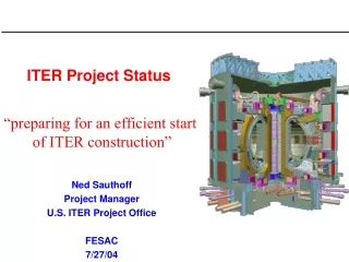
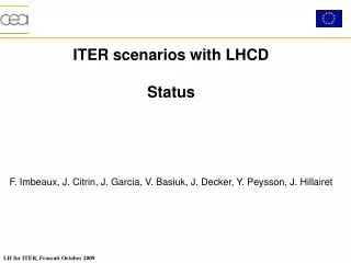
ITER scenarios with LHCD Status F. Imbeaux, J. Citrin, J. Garcia, V. Basiuk, J. Decker, Y. Peysson, J. Hillairet
Integrated ITER scenario modelling with LHCD • Results obtained earlier this year : stand-alone LHCD modelling using fixed parameters (equilibrium, plasma profiles) • 4 situations analysed • H mode baseline scenario 2 • Hybrid scenario • Steady-state scenario 4 • Current ramp-up phase • Conclusion : n//0 ~ 2.0 is an optimum design for all scenarios • Now : analyse the effect of LHCD in ITER scenarios, using integrated modelling • Current profile control • Flux saving • Tools : CRONOS + C3PO/LUKE integrated simulations
H-mode baseline scenario 2 • From stand-alone studies : poor penetration of LH waves due to high density • Flux saving during the main heating phase to quantify • Detrimental impact on Q expected (stiff transport model / pedestal) • Main application of LHCD is during the pre-heating phase : control the shape of the target current profile current ramp assisted by LHCD
Hybrid scenario • Hybrid scenario targets longer plasma duration ( > 400 s), is interested by flux saving • And by q-profile control : maintain no or small sawteeth to avoid triggering deleterious NTM minimise the size of the q = 1 surface NB : scaling-based transport model, pure gyro-Bohm DS03, non-stiff pedestal quite optimistic LH 20 MW LHCD delay significantly the occurrence of q = 1 [F. Imbeaux, PPCF 2005]
Hybrid scenario Non-inductive current drive profiles • Possible caveate : dependence of transport on magnetic shear • GLF23 : stiff model, pedestal fixed reacts strongly to changes in the threshold, weakly on change of heating • LHCD far off-axis : decreases magnetic shear off axis increases transport 33 NBI / 20 EC / 17 LHPfus= 273 MW, H98 = 1, Ip = 11.8 MAt(q=1) = 1220 s33 NBI / 37 ECPfus = 348 MW, H98 = 1.07t(q=1) = 1050 s [J. Citrin, EFTC 2009]
Steady-state scenario • Issue : the steady-state scenario is loosely defined on ITER: • Strong bootstrap current fraction required to reach full non-inductive current drive operate at low current + • + assuming the establishement of a strong ITB high uncertainties from the transport model • Baseline scenario 4 : original design uses hLH = 0.3.1020 A/W/m2 and PLH = 30 MW. Our stand-alone ALOHA/C3PO/LUKE calculations yield hLH = 0.15.1020 A/W/m2 (with optimal directivy 70 %) and used only PLH = 20 MW • the baseline scenario 4 is based on unrealistic assumptions from the LHCD point of view
Steady-state scenario • Alternative example of an ITB scenario at Ip = 8 MA [J. Garcia PRL 2008] • ITB depends on magnetic shear need to reverse the q-profile do not drive current inside ITB no NBI • LHCD drives current outside mid-radius + ECCD@mid-radius to lock the ITB position (current alignement) ideal combination • Strong ITB can be avoided (improve MHD stability) by the cyclic scenario concept [J. Garcia et al, submitted] • Only PLH = 13 MW used, fboot = 70 % (quite optimistic confinement/ITB model) q-profile
Current ramp-up with LHCD • LHCD can be used to reach the desired target q-profile for any scenario + flux saving • Extensive simulations with DINA-CRONOS-DELPHINE [Kim PPCF 2009] • Flux savings (~ 43 Wb, of which 80 % are due to heating effect) • LH dynamics : absorption close to the center at the beginning, moves outwards as Te, Ip increase
Current ramp-up with LHCD • LHCD can be used to reach the desired target q-profile for any scenario + flux saving • To be repeated with C3PO/LUKE/ALOHA in fixed boundary mode, using additional transport models • (Start LHCD earlier ? With higher power ?)
Conclusions • During the main heating phase : • Flux savings / impact on Q : to be quantified for the inductive scenarios • Delay q-profile penetration / reduce size of q = 1 for hybrid scenario : ok, but impact on confinement may be deleterious (reducing magnetic shear off-axis). ECCD could also do a good job on controlling the q = 1 surface with higher shear and confinement • Ideal location of the power deposition for a steady-state scenario with ITB. LHCD is the only actuator with high CD efficiency off-axis, and is well located for ITB scenarios. However, in optimal coupling conditions, 20 MW of LHCD would drive less than 10 % of the total current. Only one scenario simulated where this is enough to sustain a steady-state ITB. The energy transport assumptions underlying such a pure steady-state scenario with Q ~ 5 are very optimistic LHCD is more likely to play a role in advanced scenarios with some remaining ohmic current, but the installed power may be marginal to reach a significant target.These scenarios are not well defined (ITB model) • During the ramp-up phase : • LHCD achieves large flux saving + control of target q-profile • Since heating is the main player, ECCD could play a similar role ?
To complete the work • Flux savings calculations for ramp-up + inductive scenarios : depend on the transport model try calculations with 2 different models (max. stiffness vs scaling based min. stiffness) • Q should be estimated for burning phases • Hybrid : evaluate the addition of 20 MW LHCD on baseline hybrid scenario (GLF23, 53 MW scenario vs 73 MW) • Ramp-up : repeat published simulations with C3PO/LUKE, use different transport models and spectrum assumption • Linear damping of LH waves of fast alpha particules in these scenarios