Download
1 / 20
200 likes | 365 Vues
Topology for High Voltage Power supply for ITER LHCD system. P. K. Sharma, P. Garibaldi, M. Goniche, T. Hoang, A. Becoulet, …. etc. Basic requirements. The conditioning, test and operation of klystron is a complex and costly process. It is be conditioned over wide range of increasing

E N D
Topology for High Voltage Power supply for ITER LHCD system P. K. Sharma, P. Garibaldi, M. Goniche, T. Hoang, A. Becoulet, …. etc.
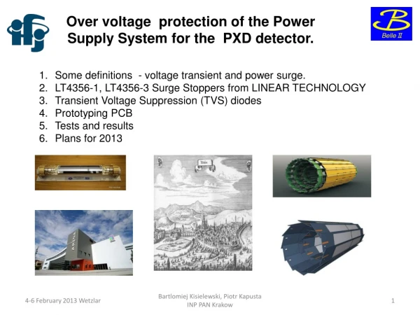
Basic requirements • The conditioning, test and operation of klystron is a complex and costly process. • It is be conditioned over wide range of increasing • voltages, • Pulsewidths, • Pulse frequency, • Input power levels • The process requires significant freedom of control of above parameters. • Conventional power supply technologies are limited in their flexibility and require significant operator knowledge and take long time before klystron reaches full performance.
Basic principle of pulse step modulator (PSM) • Series connected ‘n’ switching modules. • Each module is galvanically insulated DC PS (VDC). • Switching element (s) and • free-wheeling diode (D). Vout = n * VDC S – open => zero output S – close => VDC output
Stage rotation • Stage rotation ensures equal loading of all the modules. • FIFO (first in first out) principle is used. • For series connection it is not important which module is used because all modules are identical and output voltage just depends on total no. of modules which are ‘ON’ at a given instant of time.
Schematic of typical PSM • Galvanic insulation is achieved by using separate secondary windings on a mains transformer for each modules. [1] Alex J,Schminke W.Fast Switching,Modular High-voltage DC/AC-power Supplies for RF-amplifiers and Other Applications[C].Fusion Engineering,1995.SOFE'95.'Seeking a New Energy Era'.,16th IEEE/NPSS Symposium,1995,2:936-939
What changed our life • Physicist loves anything like f(, t) !!!! • Capability to have switches which can be • Turned ON/OFF on fast time scales (t) and • At higher frequency () • Solid state switches have done this magic. • IGBT’s are the best choice because of its ability to handle large voltages/currents, low ON-state power loss and can be switched upto 25 kHz.
General schematic of PS module Vout Added to the total output voltage Q1 & Q2 must NEVER be ON simultaneously. Q2 open & Q1 open => module is OFF. Q2 closed & Q1 open => voltage appears at Vout. Simultaneously open all series switches (Q2) & then close parallel switches (Q1). Operations ~ 2-3 usec. Vac Each module has LR filters for *smoothing the ripple, *limiting didt and Ipeak during arc, *correctly damped overall system Each module is designed for ~1.2 kVDC [2] G. Taddia et. Al., Proc. FEL 2006, BESSY, Berlin, Germany, pp-633-636.
Characteristics of PS modules • Each module is designed for ~1.2kVDC (~100A). • 100 kV DCPS involves series connection of ~100 modules, with control criteria to regulation, pulse modulation and fast switch-off (<10us). • Aims to enhance reliability, decrease costs, plug-in modularity, provide redundancy, component de-rating, component standardization and easy availability. • Relatively high complexity of Tx-former & cabling. • Module components are low voltage devices, low cost and Each stair of voltage is lower than the allowable p-p ripple, additional degree of freedom in the dimensioning of output filter.
Schematic of proposed HVDCPS Each PS cater to 4 klystrons with DC switch
Similar scheme may be duplicated for future upgrades (180 MVA margin still exists for sharing/upgrade) Schematic of HVDCPS Step-down matching Tx-former 400kV/69kV (300MVA) HVDC Switches FL # 01 Multi-secondary Tx-former 22kV/1.0kV (10 MVA) Solid-state IGBT based HVDCPS-1 100kV/100A Gas Insulated Switchgears (GIS), cable terminals and protection units like, disconnecting switches, earthing switches, surge arresters and gas circuit breaker Relay protections GIS k1 k2 k3 k4 69 kVAC distribution line Step-down matching Tx-former-1 69kV/22kV (60MVA) Feeder lines (FL) placed indoor Multi-secondary Tx-former 22kV/1.0kV (10 MVA) Solid-state IGBT based HVDCPS-6 100kV/100A GIS FL # 06 Step-down matching Tx-former-2 69kV/22kV (60MVA) Duplicate Can be placed outdoor
Main building blocks of PS The HVDC power supply consists of :- • Input circuit breaker: With a protection relay, to connect the PS to the medium voltage grid (22kV, 50 Hz, 3-ph) through a soft start equipment. • Multi-Secondary Tx-former system: To provide input voltage from grid to the voltages required by downstream parts with proper insulation level. • Power modules: In series connection, to transform AC supply voltage from transformer system to regulated DC voltage. • Control electronics: To provide regulation, protection & interface.
DC Switches • The same IGBT’s or MOSFET’s can be used for DC switches. • It replaces conventional crowbar system.
Solid state switch • These switches typically open/closes in less than 100-500 ns, depending on their power rating and can provide arc protection within 10 usec. • The opening/closing of switch is controlled by a command signal at low voltages. • For high voltages (current), series (parallel) them or in combination to meet specific requirements. • Solid state switches provides a fast, high current series switch or circuit breaker.
Typical wire-burn test result Response time ~ 1.5us Typical time history of current 50 kV/div 700A 200A 250 A/div [3] Ian, S. R., et. al., Proc. 2001 Particle Accelerator Conference, Chicago, 1459-1461, 2001.
Arc Fault capture • For pulsed system, series switch is used for both pulse modulation and arc protection. • An arc occurred at 10us during pulse. • The over current was sensed and voltage removed by opening the series switch. 5 kV/div 20 A/div [4] Ian, S. R., et. al., Proc. EPAC 2002 Paris, France, 2484-2486, 2002.
Our main requirements • Step-down matching tx-former (69kV/22kV/60MVA) [ 2 nos.] • Multi-secondary tx-former (22kV/1.0kV/10MVA) [12 nos.] • Protection circuits (GIS, VCB, etc.) • HVDCPS (100kV/100A) [12 nos.] • HVDC switches (100kV/25A) [48 nos.]
Conclusions • The continuous developments of solid state devices, available for both higher voltages and higher switching frequencies have highlighted several advantages of fully static solutions which could easily replace traditional system based on vacuum tubes. • A HVDCPS for ITER-LH system is proposed based on these developments. • The proposed HVDCPS is based on series connection of elementary power modules which do not require direct series connection of semi-conductors. • Each module has its own DC PS & voltage is evenly shared. • The output voltage is controlled by the number of switched-on modules in quantization steps of voltage. • This modulation implies averaged power distribution & minor stress of main transformer. • Each klystron has its own dc switch for protection under fault conditions. • Second level of protection is provided by main DCPS, which can be tripped sensing over current condition during fault conditions.