Download
1 / 24
240 likes | 305 Vues
Learn about overvoltage protection for the PXD detector power supply system, including surge stoppers, TVS diodes, and testing results from 2013. Understand principles of suppression and application notes for diodes. Explore layouts and schematics for protection channels. Discover plans for future prototypes and integration with the power supply system.

E N D
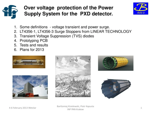
Over voltage protection of the Power Supply System for the PXD detector. • Some definitions - voltage transient and power surge. • LT4356-1, LT4356-3 Surge Stoppers from LINEAR TECHNOLOGY • Transient Voltage Suppression (TVS) diodes • Prototyping PCB • Tests and results • Plans for 2013 Bartlomiej Kisielewski, Piotr Kapusta INP PAN Krakow
Over voltage and over current can occur because of: • failures of the Power Suppies • lightning • switching transients • inductive kickback – inductive load • shorts and other problems in power wiring • What are transients and surges ? • Transients as being very fast, but with low total energy < 8.4 ms • Surges being slow,prolonged, and with high total energy > 8.4 ms • DEPFET we protect from: • failures of the power supply – surges - • -transient from fast load varation Bartlomiej Kisielewski, Piotr Kapusta INP PAN Krakow
Principle of suppression: • A blocking device detects excessive current flow, and increases itsresistance sharply to hold the load current below some limit. • A shunting device detects excessive voltage, and switches to a lowimpedancestate so that the excess current goes through it, and not through the load. Bartlomiej Kisielewski, Piotr Kapusta INP PAN Krakow
Transient Voltage Suppression Diode Application Notes Bartlomiej Kisielewski, Piotr Kapusta INP PAN Krakow
Sensitive are DHP and DCD chips for over voltage. Negative Voltages Bartlomiej Kisielewski, Piotr Kapusta INP PAN Krakow
OVP test board – 12 channels protected. Two-layers board. Without monitoring and control analog digital steering gate is bypassed Bartlomiej Kisielewski, Piotr Kapusta INP PAN Krakow
Test setup Voltage Regulator Load OVP PCB Bartlomiej Kisielewski, Piotr Kapusta INP PAN Krakow
Simplified layout of one channel sense Voltage Regulator power Front End 15 m 1.8V/2.3A OVP Module Bartlomiej Kisielewski, Piotr Kapusta INP PAN Krakow
Schematic of over voltage protection channel Load TMR Fault Timer Input Differential Amplifier sense Bartlomiej Kisielewski, Piotr Kapusta INP PAN Krakow
„for short transient in duration” Bartlomiej Kisielewski, Piotr Kapusta INP PAN Krakow
„for long transient in duration” Bartlomiej Kisielewski, Piotr Kapusta INP PAN Krakow
Digital control of the Over Voltage Protection board Small, SMD optocouplers are not common. Digital Domain Xilinx CPLD Status bits are sent to the uC, reset (re-enable) bits are sent to the channels. Analog Domain Can the reset (re-enable) signals be common for the single domain ? Gate Domain Should we latch error signal “in the channel” or in the Xilinx (with enable-disable option) ? Steering Domain uC signals Digital optocouplers Bartlomiej Kisielewski, Piotr Kapusta INP PAN Krakow
What next ? • to test prototype with PS system – some channels • design next prototype which will fit to last version • PCB • integration with PS System Bartlomiej Kisielewski, Piotr Kapusta INP PAN Krakow
Thank you Dankscheen Xie xie Arigato Danke Dekuji Dziekuje Gracias Bartlomiej Kisielewski, Piotr Kapusta INP PAN Krakow
Backup Bartlomiej Kisielewski, Piotr Kapusta INP PAN Krakow
LTspice Symulation LT1970 Power Op Front End Electronics LT4356-3 Surge Stopper with Fault Latchoff LT1809 Low Distortion Op Amps Bartlomiej Kisielewski, Piotr Kapusta INP PAN Krakow
input load voltage or current fault Bartlomiej Kisielewski, Piotr Kapusta INP PAN Krakow
Digital Domain to Front End Electronic from Voltage Regulator DVDD DCD 1.8V/1A FAULT(3.5V) UNDERVOLTAGE DHPCORE 1.2V/580mA FAULT (1.6V) UNDERVOLTAGE DHPIO 1.2V FAULT(3.5V) UNDERVOLTAGE DVDD SW 3.3V/24mA FAULT UNDERVOLTAGE Digital_Ground DGND Bartlomiej Kisielewski, Piotr Kapusta INP PAN Krakow
Analog Domain from Voltage Regulator to Front End Electronic AVDD DCD 1.8V/2.3A FAULT(3.5V) UNDERVOLTAGE REFIN DCD 1.1V/360mA FAULT UNDERVOLTAGE AmpLow 0.35V/-1A FAULT UNDERVOLTAGE VSOURCE 0V to 7V/100mA FAULT UNDERVOLTAGE Analog_Ground AGND Bartlomiej Kisielewski, Piotr Kapusta INP PAN Krakow
Gate Domain from Voltage Regulator to Front End Electronic GATE ON 1,2,3 -3V to -13V / 60mA FAULT(30 V) UNDERVOLTAGE GATE OFF -3V to +5V / 60mA FAULT(10 V) UNDERVOLTAGE VCCG 1,2,3 -10V to+1V / 10mA FAULT UNDERVOLTAGE Gate_Ground GGND Bartlomiej Kisielewski, Piotr Kapusta INP PAN Krakow
Steering Domain from Voltage Regulator to Front End Electronic CLEAR ON 7V to 25V / 60mA FAULT(30 V) UNDERVOLTAGE CLEAR OFF 0V to 5V / -60mA FAULT(10 V) UNDERVOLTAGE VBULK 5V to 15V / 10mA FAULT UNDERVOLTAGE FAULT UNDERVOLTAGE VBP (back plane) -20V VGUARD -7V to 0V FAULT UNDERVOLTAGE VDRIFT -12V to -5V SUB SUB+3.3V 0.06mA Steering_Ground SGND Bartlomiej Kisielewski, Piotr Kapusta INP PAN Krakow