Download
1 / 13
130 likes | 272 Vues
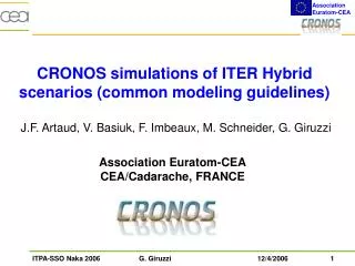
CRONOS simulations of ITER Hybrid scenarios (common modeling guidelines). J.F. Artaud, V. Basiuk, F. Imbeaux, M. Schneider, G. Giruzzi. Association Euratom-CEA CEA/Cadarache, FRANCE. Modeling guidelines. Global parameters. I p = 12 MA, B T = 5.3 T, b N ≈ 3, plasma in flat-top phase

E N D
CRONOS simulations of ITER Hybrid scenarios (common modeling guidelines) J.F. Artaud, V. Basiuk, F. Imbeaux, M. Schneider, G. Giruzzi Association Euratom-CEA CEA/Cadarache, FRANCE
Modeling guidelines • Global parameters • Ip = 12 MA, BT = 5.3 T, bN ≈ 3, plasma in flat-top phase • fD/(fD+fT) = 50%, fBe = 3%, fAr = 0.12%, tHe*/tE = 5 (Zeff ~ 1.6) • PNBI = 33 MW (0.9 MeV), PICRH = 20 MW (53 MHz,2 T harmonic) • PECRH, PLH to be determined • Profile parameters • ne profile fixed, pedestal fixed • rped = 0.925, nped= ne(0), Tped varied to obtain bN • ne(0) = 0.95 1020 m-3 , flat for 0 < r < rped , • linear drop from rped to r = 1, ne(r = 1) = 0.35 ne(0) • heat transport model: GLF23
Modules used in the CRONOS simulation • NBI: Sinbad • ICRH: Pion • Fusion power: analytical cross-section (SPOT will be used later on) • GLF23 • Synchrotron loss: EXATEC* • * Module developed by J. García, Universitat Politecnica de • Catalunya, Barcelona (Spain). Main features: • accurate expressions of the EC absorption coefficients • wall reflections (coefficient: 0.7) • it reproduces the most accurate global scaling of synch. loss
Synchrotron loss computed by EXATEC in CRONOS (J. García)
co-ECCD with equatorial launcher /1 Launch (cm): R Z ftor 820 124 30° 834 62 30° 820 0 25° PECCD = 21 MW IECCD = 0.55 MA
co-ECCD with equatorial launcher /2 Launch (cm): R Z ftor 820 124 40° 834 62 40° 820 0 40° PECCD = 21 MW IECCD = 0.45 MA
LHCD vs counter-ECCD(13 MA, Tped = 8 keV case) • +20 MW of additional heat source yields about + 1 MA of bootstrap (w.r.t 53 MW case). • LHCD off-axis because of high Tped (~ 8 keV); RT/FP calculation yields 1.1 MA of LHCD • Counter-ECCD at rho = 0.1 (assumed, with 0.375 MA ctr-CD) • q = 1 appears at 1040 s for LH and EC cases, (650 s for 53 MW) • Flatter q-profile for ctr-ECCD • Flux consumption much higher for EC case : 14.5 Wb / 1000 s flat-top vs 8.6 Wb / 1000 s flat-top for LH case • li = 0.62 vs 0.53 for LH case