Download
1 / 34
340 likes | 637 Vues
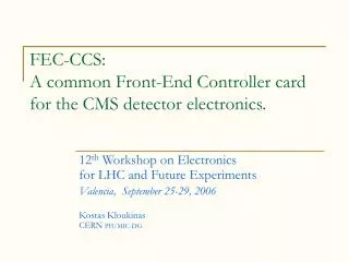
FEC-CCS: A common Front-End Controller card for the CMS detector electronics. 12 th Workshop on Electronics for LHC and Future Experiments Valencia, September 25-29, 2006 Kostas Kloukinas CERN PH/MIC-DG. Outline. FEC-CCS Design Architecture Sub-system integration phase

E N D
FEC-CCS: A common Front-End Controller card for the CMS detector electronics. 12th Workshop on Electronics for LHC and Future Experiments Valencia, September 25-29, 2006Kostas KloukinasCERN PH/MIC-DG
Outline • FEC-CCS Design Architecture • Sub-system integration phase • Production Testing • Summary Kostas Kloukinas CERN PH/MIC-DG
Front-End Control System Overview • Main Functionalities: • Establishcontrol bi-directional links with the Front-End chips. • Setup/configure FE chips. • Read back status information from FE chips and monitor detector environmental parameters. • Distribute Fast Timing signals to the Front-End chips • 40MHz LHC clock • Trigger commands Kostas Kloukinas CERN PH/MIC-DG
DOH DOH CCU Front-End Control System Overview Front-End Off-Detector FE boards FEC-CCS CCUQPLL-PLLDCU CCUQPLL-PLLDCU CCUQPLL-PLLDCU Token Ring board Optical Link mFEC VME CCUQPLL-PLLDCU ElectricalControl Ring mFEC CCUQPLL-PLLDCU clk, LV1,I2C ECAL Bus TTC CCUQPLL-PLLDCU CCUQPLL-PLLDCU CCUQPLL-PLLDCU • TRACKER • ECAL • Preshower • PIXELS • RPCs • TOTEM A common CMS Front-End Control System Kostas Kloukinas CERN PH/MIC-DG
CMS FEC-CCS System • A common Front-End controller card for the CMS sub-systems. • Advantages: • Minimize design effort and production cost. • Maximize system maintenance and support services. • Requirements: • Accommodate the differences of the CMS sub-systems architectures. • Modular design. • Flexibility. • Conform to the CMS VME electronics specifications. • The VME FEC-CCS card primary users • TRACKER : FEC (Front End Controller) • ECAL : CCS (Clock & Control System) Kostas Kloukinas CERN PH/MIC-DG
mFEC mFEC mFEC mFEC mFEC mFEC mFEC mFEC VMEinterfaceFPGA Local Bus VMEbus JTAG Fast Timing signals TriggerFPGA QPLL TTCrx ECAL TTC/TTS bus FEC-CCS Block Diagram • VME 9U, VME64x compatible. • Modular design: • 1 ~ 8 control rings per board. • Control information passes through the VME bus. • Fast Timing Signals passes through the TTC link. TTC link Kostas Kloukinas CERN PH/MIC-DG
The FEC-CCS Card VME Interface FPGA mFECs VME bus • Power consumption: • (8 mFECs installed) • 7A @ 3.3V, • 1A @ 5.0V • Total power: ~30W ECAL bus TTC input Trigger FPGA Kostas Kloukinas CERN PH/MIC-DG
The mezzanine FEC (mFEC) • mFEC Functionality • Token Ring Controller • Data Link synchronized to the LHC clock • Data Link raw throughput: 40Mbps. • Trigger Commands encoded on the clock line. • 100 (LV1A) • 110, 101, 111 • Dual Rings for redundancy • Local Bus interface through TX/RX FIFOs • Local Bus • 40 MHz, 32 bit multiplexed. • 4 bit geographical address. • 16 words address space . • JTAG port for Firmware upload • Firmware resides on the carrier board. • No configuration Jumpers. • Can be plugged onto different types of carrier boards • VME FEC-CCS cards • PCI carrier cards FPGA OPTOBAHN Ring_A Ring_B Local Bus Clk+L1 Ring_A Ring_B JTAG Kostas Kloukinas CERN PH/MIC-DG
VME Interface FPGA VME Interface FPGA VME bus • Functionality • VME to Local Bus Bridge • Support for VME64x Plug & Play functionality. • Support for Interrupt driven data transfers. • Support for VME DMA transfers. Local Busmaster VMEinterface Local Bus mFEC Interrupt Handler IRQ0 IRQ8 IRQ IRQ0 mFEC IACK IRQ1 mFEC IRQ7 IRQ8 Trigger FPGA Kostas Kloukinas CERN PH/MIC-DG
Fast Timing Functionalities • Distribute Clock & Trigger Commands to the FE electronics. • Mapping of TTC B-channel commands to Control Ring Trigger Commands. • Monitoring of incoming TTC B-channel commands. • Masking of individual TTC B-channel commands. • Generate a local 40MHz clock in the absence of the TTC signal. • Automatic selection of Remote/Local Modes. • User programmable Forced Local Mode. • Generate Local Trigger Commands • To support debugging during system integration & commissioning. • To support the operation of stand alone setups (without TTC system). • Provide support for the ECAL special TTC/TTS bus and functionalities • TTC signal fan-out to the DCC & TCC VME modules. • TTS signal fan-in from the DCC & TCC VME modules. • Interface with external equipment via NIM I/O signals. Kostas Kloukinas CERN PH/MIC-DG
Multi I/O Board 4 NIM/TTL level translators IN 4 OUT TTS signal Merger Clock out TTC Encoder L1 B<7:0> TTC signals to ECAL bus The Trigger FPGA Trigger FPGA Local Bus Trigger CommandManager Local Businterface Clk40+L1to mFECs L1 Control Ring Clock Encoder 110 101 L1ACCEPT 111 TTCrx BRCST<7:2> 40MHz TTC in QPLL 80MHz 160MHz Kostas Kloukinas CERN PH/MIC-DG
FEC-CCS Multi I/O board NIM I/O 4 Inputs 1 clock out 4 Outpus • Provides synchronization with external equipment. • 3U Rear VME Backplane Transition Board • Connects on VME RJ2 connector. VME RJ2 connector Kostas Kloukinas CERN PH/MIC-DG
Trigger Command Manager • Mapping of TTC B-channel commands to Control Ring Trigger Commands • Control Ring Trigger Command Assignments are not common for all the subsystems. • The decoding of these commands by the Frond-End ASICs is hardwired. Kostas Kloukinas CERN PH/MIC-DG
Solution: Mapping of TTC B channel commands to Control Ring Trigger Commands can be done using a LUT in the Trigger FPGA. Trigger Command Manager Sub-System IDentification register (4-bits). to Control Ring Encoder L1 Kostas Kloukinas CERN PH/MIC-DG
FEC-CCS card Trigger Latency Trigger Latency = 5 BX from TTC input to mFEC output TTCci L1A out TTCrx latency = 3 BX FPGA latency = 2 BX TTCci CLK out VME FECmFEC CLK_OUT_P FEC latency = 5 BX Kostas Kloukinas CERN PH/MIC-DG
Local Trigger Generation Logic • Functionality needed in stand alone DAQ system setups,without a TTC system support. • Generic Logic architecture • Instead of a hardwired trigger logic customized for a specific test setup,a flexible, user configurable trigger logic, is implemented. • The Physicists and Engineers can configure the Trigger Generation logic as required for each test system setup. • Flexible and configurable logic • Generation of • Single trigger commands. • Bursts of trigger commands. • Single shot sequences of trigger commands. • Periodic sequences of trigger commands. • Programmable delays for the timing of the trigger commands. • Synchronization with external signals. Kostas Kloukinas CERN PH/MIC-DG
Local Trigger Generator • Modular design • 8 identical “command channels”. • 4 Control Ring command channels. • 4 Auxiliary command channels. • Trigger Command sources • User selectable • External signals • Internal signals • Software (VME) • Trigger Command outputs • Control Rings • ECAL bus • NIM Outputs Kostas Kloukinas CERN PH/MIC-DG
Local Trigger Generator 4 Trigger Command channels Clk40+L1to mFECs LOC_L1 Control Ring Clock Encoder LOC_101 LOC_110 LOC_111 TTC signal to ECAL bus LOC_L1 TTC Encoder LOC_xxx 4 Auxiliary Command channels LOC_OUT1 NIM Outputs LOC_OUT2 LOC_OUT3 to external equipment LOC_OUT4 Kostas Kloukinas CERN PH/MIC-DG
Local Trigger Generator • 4 External Input Channels • Event rate prescaling. • 1 Generator for Periodic Events • Emulate LHC Orbit signal. NIM Inputs from external equipment Kostas Kloukinas CERN PH/MIC-DG
Results from Field operations • Local Trigger Generation Logic use in ECAL system setups: • ECAL Test Beam run 2004. • Supermodule Integration Hall (Bldg. 867). • H4 Cosmic calibration stand. • H4 ECAL Test Beam stand. • H2 ECAL+HCAL Test Beam stand. • MTCC (Magnet Test Cosmic Challenge) run 2006. • Local mode used for debugging. Remote mode used with TTCci. • Typical Operations • Pedestal Run • Software programmed periodic L1 triggers. • Electronics Calibration Run • Sequence of FE charge injection commands followed by delayed L1 trigger. • Laser Calibration Run • Command the firing of Laser pulser. Receive trigger from Laser apparatus. • Test Beam Run • Receive external trigger from counters and NIM logic. Kostas Kloukinas CERN PH/MIC-DG
TTCrx TTCrx TTCrx TTCrx TCC TCC TCC TCC The CMS ECAL case TTC link TTS link DAQ and Control cards coexist in the same crate. • ECAL TTC/TTS bus: • Distribute TTC signal • PECL • Merge TTS signals • LVDS • Bus Length: • Endcap: 3 VME slots • Barel: 6 VME slots • ECAL system • EB (Barel) 36 FEC-CCS cards • EE (Endcap) 18 FEC-CCS cards TTCrx TTCrx DCC FEC- CCS ControlRings DAQ Data Trigger Data DCC: Data Concentrator Card TCC: Trigger Concentrator Card FE Kostas Kloukinas CERN PH/MIC-DG
The CMS ECAL case • 5 different setups in operation: • Supermodule Integration Hall (Bldg 867) • H4 Cosmic calibration stand • H4 ECAL Test Beam stand • H2 ECAL+HCAL Test Beam stand • MTCC (Magnet Test Cosmic Challenge) Kostas Kloukinas CERN PH/MIC-DG
LTC APVE The CMS Tracker case Separate DAQ and Control system crates. • CMS Tracker System • 4 FEC crates • 1 crate per partition • 11 FECs per crate TTCci TTCex TTC crate (xN) FED FED FED FED TTCoc (xN) FMM crate TTS signals FE modules FED crate (xN) FEC FEC FEC TTCoc FEC crate Kostas Kloukinas CERN PH/MIC-DG
The CMS Tracker case • Tracker electronics system setups: • Electronics System integration center, bldg. 904 • Tracker Integration Facility (TIF), bldg. 186 • TOB (Tracker Outer Barrel) • TIB (Tracker Inner Barrel) • TEC+ (Tracker End Cap +) • Aachen • TEC- (Tracker End Cap -) • Firenze/Pisa • TID (Tracker Inner Disk) • MTCC test results • Validation of Front-End configuration procedures. • Validation of the Control Ring Redundancy. • Successful integration with the global TTC system. • Validation of the Tracker Trigger Throttling control loops. • APVE loop (APV emulator module) • FMM loop (TTS signals) Kostas Kloukinas CERN PH/MIC-DG
The CMS Tracker case Tracker Integration Facility CERN building 186 Kostas Kloukinas CERN PH/MIC-DG
Other CMS subsystems • Preshower • 20 FEC-CCS cards, 54 mFECs • Use of ECAL bus and special functions. • PIXELs • 16 FEC-CCS cards, 80 mFECs • Special mFEC firmware for PIXEL specific Control Rings. • Special functions implemented on Trigger FPGA firmware. • RPCs • 4 FEC-CCS cards, 25 mFECs • System used only for FE electronics control. • Timing distribution is done with on-detector TTCrx chips. • TOTEM • 4 FEC-CCS cards, 16mFECs • Use of ECAL bus and special functions Kostas Kloukinas CERN PH/MIC-DG
FEC-CCS Production Testing • In-house Production Testing. • CERN ECAL Lab. Bldg. 11. • Custom made production test bench. • Test bench hardware based around a VME crate. • Test bench software prepared by Evgueni Vlassov. • Operated by a technician. • Same test bench used for both mFEC modules and VME FEC-CCS cards production testing. Kostas Kloukinas CERN PH/MIC-DG
Production Test Bench TTCvx Optical Loop Back cable TTCvi SBS bridge JTAG cable 40.080MHz WINDOWS PC clk Frequency Generator FPGA programming A B CERN scientific Linux >_ ECAL backplane tester Winner 9U VME crate LINUX PC Test program TTC link Kostas Kloukinas CERN PH/MIC-DG
Production Testing Procedure Test all mFECs on a selected VME FEC-CCS card Debug rejected mFECs Test VME FECs using a set of 8 selected mFECs Debug rejected VME FECs Kostas Kloukinas CERN PH/MIC-DG
FEC Production Status • mFEC Final Production: Completed • 900 modules tested. • 35 rejected modules • Post-production run of 50 modules to compensate • VME FEC-CCS Production: Testing in Progress • Pre-production volume: 40 boards • Distributed to ECAL, Tracker, Pixels, Preshower & RPCssub-systems to equip their DAQ test setups. • These boards will also be used to equip the final systems in CMS. • Final production volume: 130 boards • Assembled PCBs delivered at CERN • Production testing is in progress. • Estimated delivery period ~10/2006. mFEC FEC-CCS Kostas Kloukinas CERN PH/MIC-DG
A common module for CMS • 60 cards already distributed to the CMS sub-system groups. • Installed in various test systems at CERN and external institutes. • PIXEL group received full production cards Kostas Kloukinas CERN PH/MIC-DG
FEC Common Software Detector Run Control (Supervisor) • FEC Common Software • Provide access to the common hardware • Facilitate Maintenance and User Support • Features • Multi-Layered software. • Support several types of FEC hardware (PCI, VME, USB) • FEC Common Software development team: • Frederic Drouhin (Tracker) • Laurent Gross (Tracker) • Evgueni Vlasov (ECAL) • Wojciech Bialas (Preshower) • FEC Supervisor • Configuration • DCU readout Subsystem Specific Software Common Generic Library Management of several Rings Management of one Ring Management of Hardware VME, PCI, USB FEC hardware VME-FEC, PCI-FEC, USB-FEC Kostas Kloukinas CERN PH/MIC-DG
FEC-CCS User Support • Hardware • mFEC, PCI-FEC (optical, electrical), VME FEC-CCS cards. • Support: CERN MIC group. • Contact persons: Kostas Kloukinas, Christer Ljuslin and Christian Palliard. • Firmware • Unique Firmware version for all the sub-systems to ease maintenance. • New firmware releases fixes various system “glitches” and adds functionality. • Anticipate to have firmware revisions during the subsystem integration and commissioning periods. • Visit the FEC-CCS project Web Site for relevant information • http://proj-fec-ccs.web.cern.ch/proj-FEC-CCS • or GOOGLE it -> (FEC-CCS) • Software • FEC Common Software support: • Contact person: Frederic Drouhin • Provide common software user support for: • Tracker, ECAL, Preshower, Pixels, RPCs & TOTEM. • Web Page: • http://x5oracle.cern.ch:8080/JSPWiki/Wiki.jsp?page=FECSoftware Kostas Kloukinas CERN PH/MIC-DG
Summary • A common FE controller card for CMS sub-systems • Fulfils the requirements of the CMS sub-systems. • Modular hardware design and flexible firmware to accommodate the different requirements. • Successfully tested in numerous sub-system test setups. • Production testing in final stage. • Boards are being delivered to CMS subsystems. • Provide support during detector commissioning period. Kostas Kloukinas CERN PH/MIC-DG