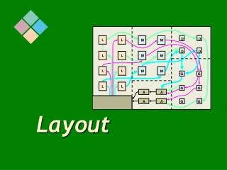
Layout, Mask, photo
Lithography. Layout, Mask, photo. Index. Quick Review Layout Basics Mask Basics Lithography Key Steps Details Optics Production. Layout, Mask & Photo. Layout Convert electrical design to physical design 2D ‘picture’ of the final chip (quantitative) Mask

Layout, Mask, photo
E N D
Presentation Transcript
Lithography Layout, Mask, photo
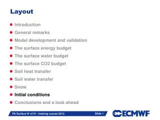
Index • Quick Review • Layout Basics • Mask Basics • Lithography • Key Steps • Details • Optics • Production
Layout, Mask & Photo • Layout • Convert electrical design to physical design • 2D ‘picture’ of the final chip (quantitative) • Mask • Creates a physical layout (similar to photo negative) • Can be used to general many chips (similar to obtaining many copies from a negative) • Photo (Lithography) • Process of obtaining a ‘picture’ from a ‘negative’ • (ie generating shapes on wafer from a mask)
Electrical Chip Design Physical “Layout” Design R C Testing Creating the chip Chip manufacturing: Snap shot Blue Print- Photo “negative” Review “Print” Quality Control
Resistor Diode N Oxide P+ Oxide Oxide P+ Oxide N Oxide Oxide Oxide Oxide Substrate (p silicon) Substrate (p silicon) Layout: Basics • Electrical circuit • Physical circuit
M1 layout Layout: Basics • Layout • Each layer is made one at a time. Hence each layer has a ‘photo negative’ or mask • Therefore, each layer must be specified separately in the ‘layout’ file. It is a computer file (softcopy) • Example • A sample part of a chip • Layout provides the top view (2D) • The ‘depth’ is controlled by the deposition process (and not by the layout)
Y2 X1 Y3 Y1 Y4 Z1 Z2 X3 X4 X2 P+ Oxide N Oxide Substrate (p silicon) Layout: Basics • Layout will provide information on x and y • Process flow sheet will provide information on z
M1 Via 12 M2 Layout: Basics • Example • A sample part of a chip • The file has different layers (numbered from 1 to...) • A table which correlates the layers to numbers is also provided
width width Dia Dia height height Lowaspectratio High aspect ratio Layout: Basics • Via and contacts are shown as squares (or in rare cases rectangles) in the layout. Others are in rectangular geometry • Cheater rules for SRAM • However, the mask will have circular (or in rare cases elliptical) holes • Completely filling rectangular features with high aspect ratio (with metal) is difficult • Aspect ratio: Depth/width (or diameter)
Layout: Basics • Hierarchy vs Flat file • Levels, Layers • GDS (stream format), GDSII, MEBES, CIF • Review • Softcopy (quantitative) • of what is ideally required • Top view (2D) only • Hierarchy
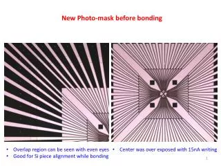
Mask: Basics • The layout file is given as ‘input’ the mask making machine • E-beam writer (electron beam) • Scans the “blank” mask • Mask may be a plate of glass, coated with chromium. On top of chromium, a photosensitive coating is applied • A mask is often referred to as ‘chrome’ • E-Beam, ‘sensitizes’ the areas • Develop the resist • Remove chromium on the ‘exposed’ areas
Mask: Basics • Relatively slow process • beam goes to each ‘pixel’ which has to be written ‘on’ • switches “on” and then “off” • moves to the next pixel which has to be written on • Mask has to be very very clean. • Any particle on the mask will cause incorrect ‘feature’ in all the chips • ==> chips will to fail • A mask is then coated with a clear film, to protect it. • Eg. If a particle falls on the mask, then you can remove the clear film and put a new film. (Easy to ‘repair)
Mask: Basics • A mask may be 100 mm x 100 mm (for example) • The size is decided by the size of the lens in the lithographic tool • A mask is usually 4 to 5 times larger than the actual feature. The features are ‘reduced/ zoomed out’ during the lithographic process • Correspondingly, a mask is referred to as ‘4x mask’ or ‘5x mask’ • Example: If you want a 100 nm wide line on the wafer • layout file will show 100 nm wide line on the screen • mask making machine will enlarge everything by 4 • Actually, layout file will be converted to another file which will enlarge it by 4 and then the mask making machine will use it. • The process is sometimes called MDP (Mask Data Preparation) • Mask will have 400 nm wide opening and • Lens in the litho process will ‘shrink’ the image to 100 nm.
Mask: Basics • A mask may be 100 mm x 100 mm (for example) • So, one ‘print’ will be about 25 mm by 25 mm, on the wafer. • A chip may be only 5 mm by 4 mm • So, one mask will have perhaps 20 chips, if the chip is small • The gaps between the ‘real chips’ are used for • alignment marks (TBD) • test structures (TBD)
Mask: Basics • If a mask gets dirty in a particular location, • with in a ‘field’, a die will always fail • may also happen due to lens issues • Pizza masks, to verify design changes
+ve resist; dark field mask -ve resist; light field mask Mask: Basics • A mask may be dark-field or light-field • Depends on the photo resist that will be used in the process • If photo resist dissolves in the exposed regions, it is positive photo resist; else negative Desired structure • Mask Review
Lithography: Overview • Shape Definition • Key steps • Details of steps • Optics: Relevant information • Production: Relevant information • Review of Lithography
Lithography: Basic steps • Coat the wafer with light sensitive material (photo-resist) • Place the mask over the wafer and align with the wafer. Adjust the focus of the camera • Expose the wafer to light (for a controlled time period) • Exposed photoresist will have changed chemically • Wash the wafer+photoresist in a solvent (Developing the resist) • Removes only exposed photo resist • Etch the ‘open’ areas • Remove all the remaining resist Animation
Lithography: Schematic • Note: Some schematics will show mask between lens and wafer. In reality, at least one lens will come between the mask and the wafer
Lithography: Basic Steps • Coat the wafer with light sensitive material (photo-resist) • Mask over the wafer, align, focus • Exposure for a precise amount of time • Move (Step) to the next ‘Field’ • Stepper • Actually, the wafer moves, not the litho system • Repeat the above procedure
Lithography: Basic Steps • After the whole wafer is exposed.... • Repeat for other wafers in the lot • Crude schematic below • Develop the lot • Etch the open areas • Remove the remaining photo resist and the etch products Note: Etch product forms a thin film or ‘veil’. Removal of the veil is called ‘de-veil’
Lithography: Details Photo Resist Coating • Mostly positive resists used now • More resistance to pinhole formation • Easier removal (stripping) • More expensive • Harder to develop (solubility differential is not high) -ve resist; most area open +ve resist; most area blocked
Lithography: Details Photo Resist Coating • Prepare the wafer • Clean the wafers (to remove particles) • Dry (150-200 C bake) • Primer (HMDS- Hexa Methyl Di Silazane) • Immersion (liquid) • Spin coat (liquid) and high speed drying • Vapor prime • Photo resist coating (spin coating) • 1 um thick (± 1% variation)
Lithography: Details Photo Resist Coating • Dynamic coating • Low rpm (500) dispense • High rpm (5000) thinning (form uniform film) • Final resist thickness depends on rpm and time • and viscosity, surface tension, drying characteristic of solvent... • Moving arm to enhance uniformity
Lithography: Details Photo Resist properties • Contains photosensitive materials, sensitivity enhancers (called sensitizers), solvent • Resolution • Contrast • Response to a given wavelength (spectral response) • Solubility differential between unexposed vs exposed regions • Etch/ Implant resistance
Lithography: Details Pre Expose Bake • Soft Bake: • To drive out the solvent • Resist is still ‘soft’, but not liquid like • Temperature: • Baking options: • Hot Plate (manual, moving) • Convection Oven (may form crusts) • Infra-red (wafer surface heated) • Microwave (volume heating) • Vacuum baking (radiation)
MASK Lithography: Details Exposure • Litho Tool (current): Projection aligners • Stepper vs Scanner • Historical: Contact, proximity aligners • Proximity: • Mask almost in contact with wafer • Mask may become dirty over time, but not as bad as contact • 1x mask, minor optical distortions • Contact: • Mask in contact with wafer • Mask may become dirty over time • 1x mask, no optical issues Wafer (with resist coating)
Lithography: Details Exposure • Litho Tool (current): Projection aligners • Stepper vs Scanner • Stepper: What we saw before • Scanner: Actually Step & Scan • Need smaller lens for the same sized mask • Or with same sized lens, can handle larger mask Stepper Step & Scan Lens Lens MASK
I G H Intensity 400 nm Lithography: Details Exposure • Light Sources • Hg Lamp: Filter • G,H, or I-line (365 nm) • Excimer Lasers (DUV) • ArF193 nm , RF 248 nm etc • EUV, X-Ray, E Beam (in R&D) • EUV: Reflective optics 600 nm
Lithography: Details Develop • Post Exposure Bake • Similar to pre-exposure bake • Help minimize standing wave effects • Developing • Immersion • Spray develop • Plasma (dry) develop • Rinse • Hard bake: 200 C, 30 mins (for example) • To protect from etch/implantation • Resist flow • Etch