Download
1 / 19
200 likes | 506 Vues
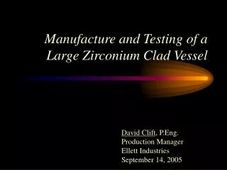
Manufacture and Testing of a Large Zirconium Clad Vessel. David Clift , P.Eng. Production Manager Ellett Industries September 14, 2005. Abstract. Serviceability depends upon the quality of the clad corrosion liner

E N D
Manufacture and Testing of a Large Zirconium Clad Vessel David Clift, P.Eng. Production Manager Ellett Industries September 14, 2005
Abstract • Serviceability depends upon the quality of the clad corrosion liner • Careful application of design details, skilled trades & systematic application of manufacturing controls and non-destructive examination.
Zirconium Clad Steel Reactor 3.6m diameter x 6.5m length (11’ 10” x 21’ 2 Shells are 22mm (7/8”) thick SA516-70 with 3mm (0.12”) nominal, 2.28mm (0.090”) minimum, thickness Zirconium 702 explosion clad liner. The hot pressed heads are of 37mm (1.5”) SA516-70 with a 4.7mm (3/16”) nominal thickness of clad liner
Design Details Separation of Longitudinal & Circumferential Welds Advantages • Containment of possible breaches • Efficient gas purging • Simplified helium testing
Material Procurement • Base Metal N.D.E. • ASME SA 578 Level C • grid pattern or continuously scanned - grid pattern is standard • three inspection levels • A- least , B - moderate, C - most demanding; allows a discontinuity smaller than can be contained within a 25mm circle • Cladding N.D.E. • full compliance with ASME Section VIII & IX • production bend tests, PT examination and 100% RT before bonding • PT after bonding and, in the case of the heads, after forming. All clad surfaces were visually examined
Ultrasonic Examination of Bonding ASTM B 898 Acceptance Criteria • Class C is the standard Inspection Class of B 898 • Class B was specified for this project
Explosive Cladding • Current Practice • an interlayer of titanium when zirconium cladding exceeds 6.4 mm (1/4”) nominal thickness • Explosion detonation (booster) locations • corner, side or center of plates • an area of ultrasonic non-bond is typically located under the detonation point • non-bond related to the size of charge
Vessel Plate Manufacture • Central explosion detonation points for both shell and head plates on this unit • thin cladding, thick backing plates • ASTM B 898 Inspection Class B ultrasonic inspection (75mm maximum indication size) • Results • non-bond areas in shell plate were acceptable • head plate detonation points were removed as cut-outs for centrally located nozzles
Plate Surface Defects • Damaged areas of clustered gouges were noted on three of the six shell plates • Gouge depth ranged from 1.2mm (0.047”) to 2.4mm ( 0.094”) deep • Gouge size varied –less than 13 cm2 (2 in2) in area • Root cause - “rock fall” that occurred during underground explosive blasting
Repair Plan • Weld repair • shallow gouges (<1.2mm deep) were weld repaired in conformance with ASTM B 898. • Controls • customer approval • carbide burr removal • qualified weld overlay repair • PT inspect • fully documented
Repair Plan - cont’d • Deep gouges • Individually ported batten style covers
Vessel Seam Weld & Test Sequence • Carbon steel welds are applied and specified NDE performed prior to batten strap attachment • UT the cladding bond adjacent to the end of the longitudinal seam filler strips to find potential leak paths • Fit & weld longitudinal batten strips, silver braze to isolate and helium bubble test @ 1 bar pressure • Circumferential welds performed in a similar manner • Confirming PT of all ZR welds per ASME
Fabrication - Cleanliness • Tool surfaces to be of alloy, plated or hardened steel • Rolls & brake forming surfaces - confirmed free of all surface defects & contamination • Weld joint design should minimize carbon steel welding & grinding on process surfaces • Zirconium weld zones are mechanically and chemically cleaned prior to welding
Final Cleaning • Contaminated areas abrasively ground • Acid wash with HF/HNO3 • Ferroxyl test per ASTM A 380 • spray application of the potassium ferricyanide test solution on suspect areas • reacts with free iron to form a blue indication
Helium and Hydro Testing • Helium Mass Spectrometer testing per ASME Section V, Article 10, Appendix IV was performed before and after hydro testing • Purging batten strip cavities • helium from bubble testing conducted up to a month earlier had to be purged with clean & dry air to eliminate false indications • Test conditions • 25% of the vessel’s maximum allowable working pressure (50 psig) • approx 20% helium concentration
Test Results • Results • All purge vents located behind nozzle liners, seams and internal batten style patches were vacuum sniffed • All readings remained at a background or atmospheric helium concentration - equivalent to a leak of 5 x 10⁻⁶ atm cc/sec
Additional Research • Preparation and analysis of a zirconium weld overlaid coupon to assess built-up metal quality • CS - TI - ZR construction After welding and step machining Prepared block – ready to weld overlay
Results • ZR overlay welding on both the titanium interlayer and the zirconium cladding, min thickness .76mm • Test results confirm a composition containing titanium and zirconium • No detectable iron was present in any of the test samples • 100% Zr when a 0.76mm thick layer was applied over a combined thickness of Ti and ZR of 3.05mm. The actual thickness of the ZR alone in this case was 1.3mm